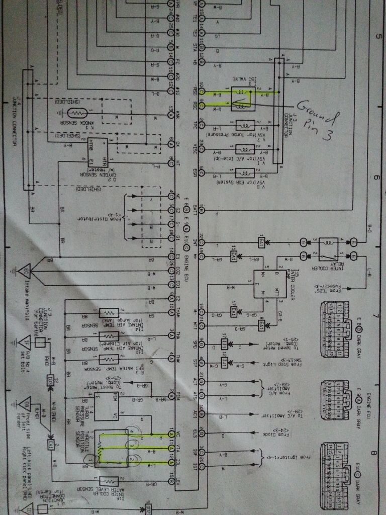
JDM Toyota Caldina GT-T (ST). 3S-GTE Generation 4. Electrical Wiring Diagrams and ECU Pinouts.
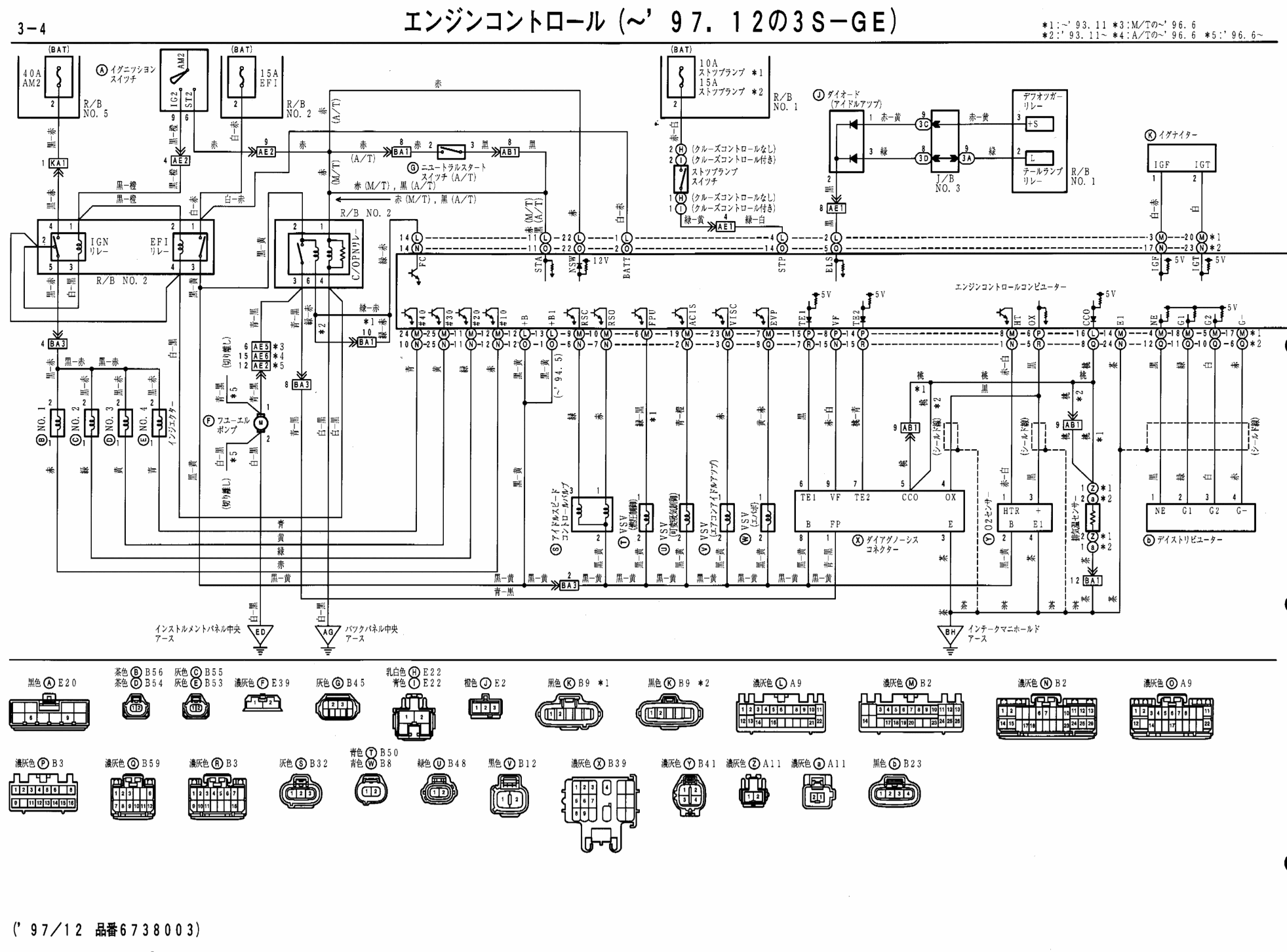
1_of_73_Caldina_Electrical STG. Toyota – ST – Electrical Wiring Diagram, (download PDF, 3MB) Toyota – ST – Service Manual (translated), (PDF, 89MB).

Toyota – Wire Harness Repair . When solenoid relay is ON Using electrical wiring diagram and check 2.
SFRH] 1. 3.
While Using diagram and check parts inspection. RR-] 34 C Rear LH.

Does anyone have a wiring diagram for a caldina st? i need to know th wire location in the mirroradjusting switch Hope someone can help.
Using electrical wiring diagram and check parts inspection, power voltage inspection, wiring and connector inspection. 1.
Confirm battery voltage is supplied.Jun 12, · ST Caldina installation I have downloaded the wiring diagram you have for the ST I notice you have it set up for MAP replacement. Would it be OK to wire it up as MAP intercept and just change the areas I need to alter, or would it be better to use MAP replacement and load the ST data you provide? Thanks.
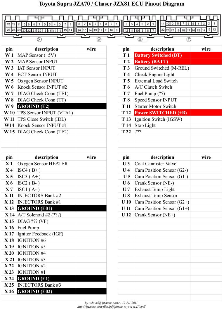
Jun 12, · ST Caldina installation I have downloaded the wiring diagram you have for the ST I notice you have it set up for MAP replacement. Would it be OK to wire it up as MAP intercept and just change the areas I need to alter, or would it be better to use MAP replacement and load the ST data you provide? Thanks. Thank you for stopping by at this website.
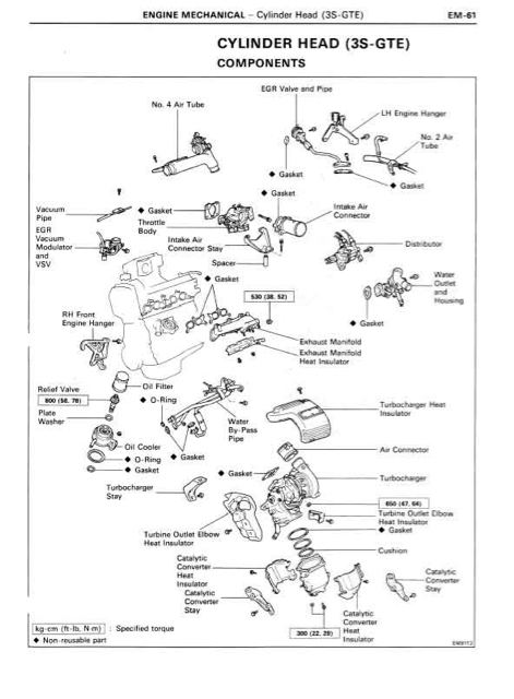
Listed below is a excellent photo for 3sgte st wiring schematron.org have been searching for this picture through on line and it came from professional resource. Apr 10, · If you are still looking for verification on those st diagrams, those were what I used for the gen4 harness I did back in December.
We have had the car running with no codes for a few weeks schematron.org the fivebob diagrams and pinouts are valid. Apr 24, · EGO: this sensor is a 4-wire narrowband on all USDM motors and is located at the turbo elbow between the turbo outlet and the downpipe. Almost all EMS units that can read a narrowband sensor can use the stock O2 sensor.

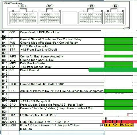
Also, it appears that the labels on the 26p, 16p and 22p connector diagrams are reversed, i.e. the JDM are the USDM.MWP’s Toyota Celica GT4 (ST, ST, ST) Documents & MediaST 3S-GTE ECU PIN
