When wiring a 470017 float-based device, the primary goal is to ensure reliable operation of the water level sensor system. Follow a systematic approach to avoid electrical errors and achieve stable functioning. First, ensure that all connections are secure, especially the terminals that connect the sensing mechanism to the power supply. These connections are typically color-coded, making it easier to match the wires accurately to their corresponding ports.
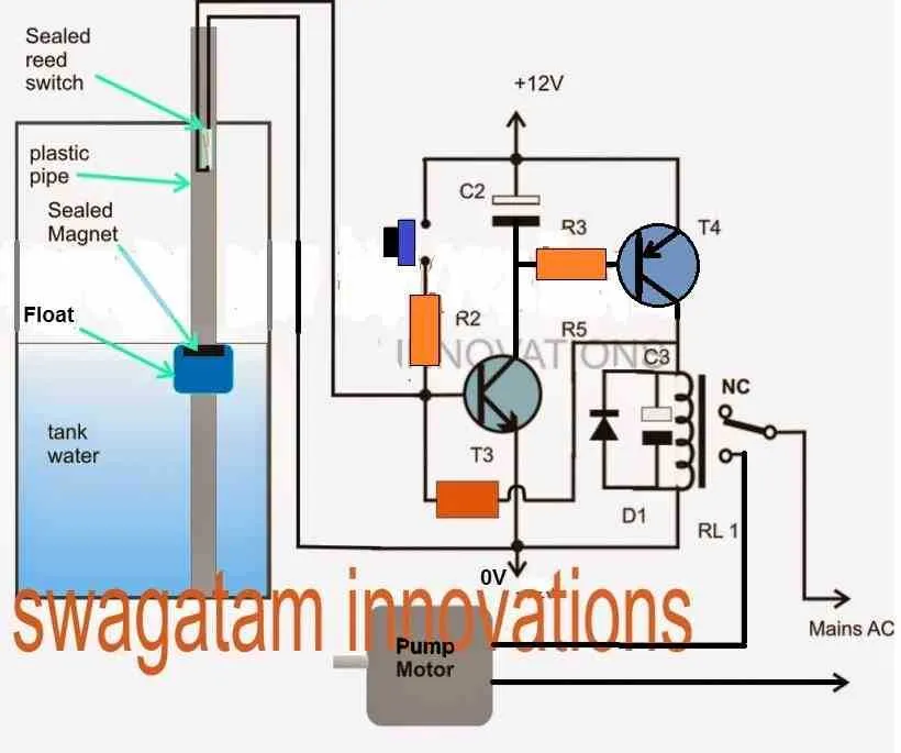
Check the configuration of the internal components of the mechanism. The sensor, often a simple on/off switch, should be positioned correctly within the container, and any floating element must move freely to activate the electrical signal. If you notice any blockage or resistance, it could prevent the system from working properly. Proper placement of the float device ensures it triggers the relay at the right water level.
Next, pay close attention to the wiring insulation and the integrity of the cable. Damage to the wires, such as fraying or cuts, can lead to short circuits or intermittent failure of the system. Verify that the insulation is intact, and use wire connectors to secure the ends of the cables, reducing the risk of disconnection or wear over time. When possible, employ waterproof enclosures for additional protection.
Finally, test the system before full installation. Once all connections are made, simulate different water levels to ensure the sensor activates at the correct points. This step will confirm that the electrical components function correctly and that the wiring is properly routed, allowing the mechanism to signal accurately when the water reaches the predetermined level.
Installation Guide for the 470017 Float Control System

For correct installation, connect the power supply to the designated terminal, ensuring that it aligns with the system’s voltage requirements. Make sure the ground connection is secure to avoid electrical hazards.
The signal cable should be attached to the input terminal, allowing the system to detect the water level changes. Use wire connectors to join the input cable to the appropriate pins and ensure a reliable connection.
It’s crucial to ensure that the mechanical components are positioned properly to avoid signal interference. The floating element must be mounted in such a way that it moves freely without obstruction.
To configure the device, ensure that the sensing mechanism is correctly positioned in the tank. The switch should be able to detect the liquid level at both high and low points, triggering the necessary response.
During testing, simulate water level changes to verify that the system responds as expected, activating the necessary actions when the level reaches preset limits. Adjust the sensitivity if needed for optimal performance.
When securing all connections, double-check for any potential loose wires or exposed connections that might cause malfunctions or shorts. Proper insulation and securing of cables are essential for long-term reliability.
Understanding the Electrical Connections for the 470017 Device
To ensure proper function, connect the terminals carefully, following the manufacturer’s guidance. Begin by linking the power supply to the designated input terminals, typically marked as L and N. These connect to the live and neutral wires of the circuit. Be mindful of correct polarity to avoid malfunctions.
Next, focus on the output connection. The two terminals intended for controlling the external device should be linked to the corresponding inputs on the equipment you’re controlling. One terminal will usually be connected to a relay or control unit, while the other connects to the load, ensuring the flow of current when the specified level is reached.
If your model features a grounding terminal, connect it to an earth ground. This step is crucial for safety, preventing electric shock in case of faults.
Verify all connections before powering the system. Miswiring can cause incorrect operation or even damage to components. Using a multimeter, check continuity and voltage at each terminal after making connections.
Lastly, for systems with adjustable settings, fine-tune the sensitivity or activation level to match the operational requirements. This can usually be done via a small screw or dial, depending on the model.
Step-by-Step Guide to Install the Sure Bail 470017 Float Switch
To install the device, follow these detailed steps to ensure proper operation:
- Prepare the Power Supply – Disconnect the power source to prevent any electrical hazards during the installation process.
- Mount the Unit – Secure the control component in a location that allows the sensor to operate efficiently. The unit should be placed at the desired water level and in a stable environment free from any obstructions.
- Connect the Cables – Attach the required cables to the terminals on the unit. Ensure that each connection is firm and properly aligned with the matching terminals. Use appropriate connectors to avoid any loose or exposed wires.
- Position the Sensor – Position the sensor at the appropriate depth within the water. Ensure it remains steady to provide accurate readings.
- Secure the Sensor Cables – Tidy up and secure the sensor cables to avoid interference with other equipment. Use cable ties or clips to fasten the cables neatly to surfaces.
- Power Up – Reconnect the power supply and check that the system is receiving power properly. Test the device to ensure it activates at the set water levels.
- Test Functionality – Run multiple tests to verify that the device responds correctly to different water levels. Adjust the settings if necessary to fine-tune the operation.
Ensure that each step is carefully followed for optimal performance and safety. If any issues arise during installation, refer to the troubleshooting section of the manual.
Common Connection Issues and Troubleshooting Tips
Check for Loose Connections: Ensure that all terminals are securely connected. Loose or corroded terminals often lead to intermittent failures. Inspect the contacts and clean them if necessary to improve conductivity.
Incorrect Polarity: Reversing the positive and negative wires can cause malfunctions. Verify the correct orientation by following the manufacturer’s instructions and using a multimeter to test voltage polarity.
Faulty Grounding: A poor or disconnected ground can lead to erratic performance. Confirm that the grounding wire is firmly connected to a proper, clean ground point. Use a multimeter to check for continuity.
Wire Insulation Damage: Inspect the insulation along the cables for any visible signs of wear or cuts. Damaged insulation can lead to short circuits or electrical faults. Replace any damaged sections immediately.
Overloaded Circuit: Overloading the system can trip internal safety mechanisms or damage components. Ensure the circuit is not drawing more current than specified. Use an ammeter to measure current flow.
Interference from Nearby Electrical Equipment: External electromagnetic interference can affect operation. Ensure that the cables are routed away from high-voltage lines or heavy machinery that may cause noise or erratic behavior.
Corrosion on Contacts: Exposure to moisture can corrode terminals and connectors, causing unreliable operation. Clean corroded parts with contact cleaner and apply a thin layer of dielectric grease to prevent further buildup.
Incorrect Voltage Supply: Ensure the device is receiving the correct voltage according to specifications. Too high or too low a voltage can cause improper function or failure. Use a voltage tester to check the incoming power.
Testing the Sensor Mechanism: The sensor itself may fail or become stuck in one position. Test its operation by gently manipulating the device to check for proper movement. If it remains stuck, it may need to be replaced or repaired.