Ensure the system is positioned close to the water source for optimal efficiency. Place the mechanical unit below the water level to facilitate smooth operation and prevent cavitation. If you need to connect multiple devices, use a well-sealed pipeline to avoid leaks and maximize pressure. Make sure to maintain a slight slope in the lines for gravity assistance.
Use a multi-valve to easily control water direction, which reduces the chances of clogs. Properly size the mechanical unit according to the flow rate and volume of water you plan to circulate, ensuring it doesn’t overwork or underperform. Always prioritize ease of access for maintenance purposes to avoid complex disassembly later.
Incorporate a debris trap at the beginning of the system to catch large particles before they reach the primary components. This will extend the lifespan of the equipment. Position the waste line for proper drainage, avoiding any potential backflow or blockages that could hinder circulation.
Lastly, secure all connections with durable materials, such as high-quality PVC or reinforced hoses, to guarantee long-term durability. Proper insulation is critical in preventing energy loss and maintaining consistent performance throughout the seasons.
Effective Setup of Circulation System Components
Ensure correct positioning of the water circulation device near the water basin to minimize piping length and maintain efficient water flow. Select a spot that is level, well-ventilated, and accessible for regular maintenance tasks. The motorized unit should be placed above the water level to avoid backflow issues and reduce the risk of clogging.
Use high-quality hoses to connect the filtration apparatus to the circulating machine. Reinforce connections with appropriate clamps to prevent leaks. Avoid excessive bends in the tubing to optimize water flow and reduce strain on the system.
Choose a filtration system with a flow rate that matches the size and capacity of your setup. Over-sized or under-sized models can cause inefficiency, either by overworking or failing to filter water adequately. Refer to manufacturer recommendations for sizing based on volume and turnover rate.
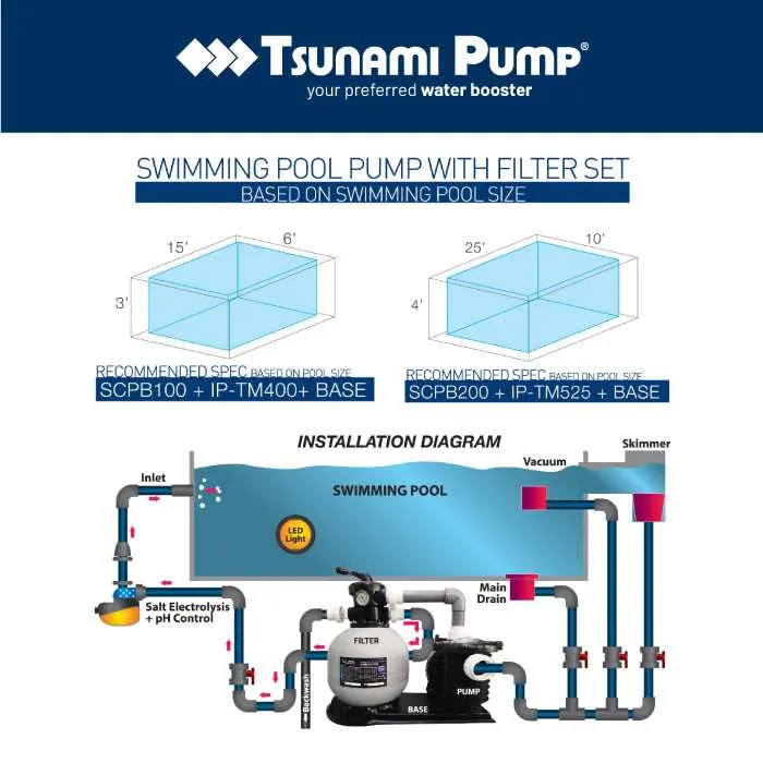
Position the intake and discharge areas properly for optimal flow. The inlet should be placed at the deepest part of the basin to ensure thorough water circulation, while the outlet should be positioned to promote even distribution of treated water.
Install a bypass valve between the two primary components. This allows for easy adjustment of water flow and pressure, ensuring system balance and preventing overloading of the filtering medium.
Regularly inspect all connections for leaks and wear, and replace any compromised parts promptly. Maintaining a clean and clear connection between components extends the lifespan of the system and enhances overall performance.
Follow manufacturer guidelines for routine maintenance schedules, including cleaning the filtration medium and checking electrical connections. Neglecting these tasks can lead to decreased efficiency and increased energy consumption.
How to Properly Position Your Equipment for Optimal Performance

Place your circulation system components at least 3-5 feet away from the water feature, ensuring they are situated in a dry, level area. This prevents water accumulation around the motor and other electrical parts. Position the unit below the waterline to minimize pressure on the intake and improve fluid flow.
Avoid placing the system in direct sunlight for extended periods. Excessive heat can degrade the materials and reduce efficiency. Use a shaded location or a protective cover if necessary.
The area should allow for clear access to all parts for routine maintenance. Ensure that hoses or pipes leading to the unit have a gentle slope to avoid any kinks or sharp bends that could impede flow.
Install the unit on a solid base like concrete or sturdy decking. Ensure that the surface is smooth to prevent vibrations, which can cause wear and tear on the equipment over time.
Take into account the local climate. If you are in an area with extreme temperatures, ensure the components are properly insulated to prevent damage from freezing or excessive heat.
Allow at least 12-18 inches of clearance on all sides of the system to facilitate airflow and minimize the risk of overheating.
Finally, consider the noise level. Choose a location that minimizes the noise disturbance, especially if you live in a densely populated area.
Key Components of the Water Circulation System

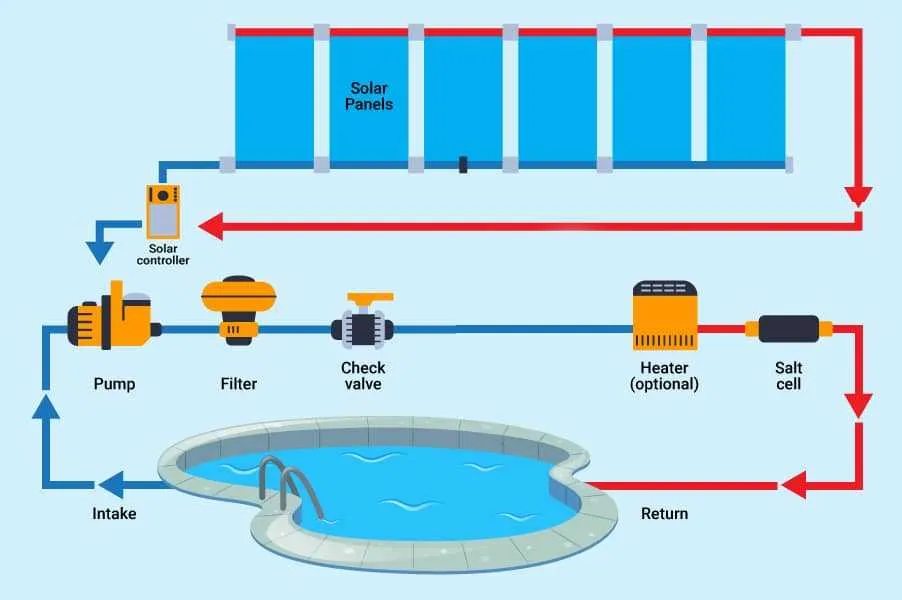
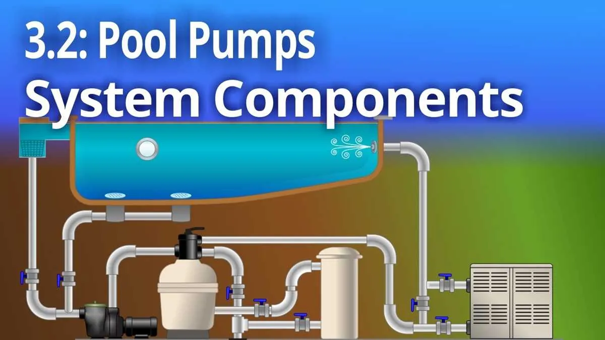
The water circulation system requires specific elements for effective filtration and circulation. Each component plays a crucial role in maintaining water clarity and chemical balance.
- Motorized Unit: This device drives the entire water flow process, creating the necessary pressure for the system’s functioning. It’s essential to select a unit with adequate horsepower for your system size to ensure efficiency.
- Impeller: Located within the motorized unit, the impeller is responsible for moving water through the system. It needs to be made of durable material to withstand debris and resist corrosion.
- Strainer Basket: Positioned near the intake, the basket traps large debris, preventing clogs in the pipes and other components. Regular cleaning is necessary to ensure smooth operation.
- Discharge Pipe: This pipe directs the filtered water back into the area. It’s important that the pipe is properly sized and routed to avoid any pressure drop and maintain optimal flow rates.
- Cartridge or Sand Holder: This element holds the medium that removes smaller particles. Choose a filtration medium that matches your system’s needs, as some types provide finer filtration.
- Multiport Valve: Allows for easy operation of the entire system, controlling functions like backwashing, filtering, and draining. Ensure it’s compatible with the unit’s specifications for seamless performance.
- Pressure Gauge: This tool helps monitor system pressure to detect potential blockages or maintenance issues. It is essential for assessing the efficiency of filtration and water flow.
- Return Jets: These outlets allow the water to flow back into the area. Proper placement of return jets can optimize circulation and help prevent dead zones where water stagnates.
- Valves: These regulate water flow through the system, offering control over different areas. Using high-quality, corrosion-resistant valves ensures long-term reliability.
- Plumbing Connections: Properly sealed and durable plumbing ensures there are no leaks. Quality materials, like PVC, are essential to avoid wear and maintain pressure consistency throughout the system.
Step-by-Step Guide for Connecting Water Circulation System Tubing

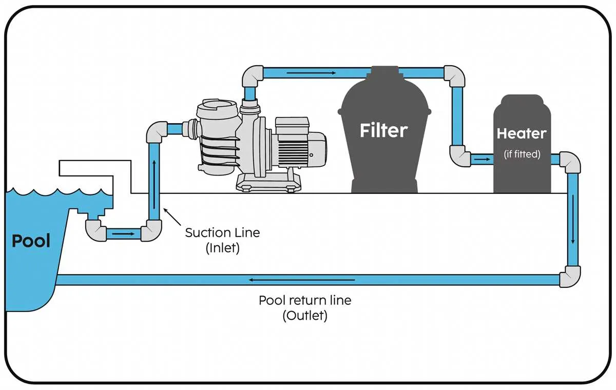
Begin by measuring the required length of hoses to connect each component. Use a tape measure to ensure accurate dimensions between the intake, filtration unit, and the return nozzle. Always add a little extra length to account for bends.
1. Attach Intake Hose
Start by securing one end of the intake hose to the inlet connection on the motor unit. Tighten the hose clamp using a screwdriver to ensure a firm fit. Make sure the hose is not twisted to avoid any kinks that could impede water flow.
2. Connect the Filtration Chamber
Next, connect the other end of the intake hose to the filtration chamber input. Secure it tightly, making sure no gaps are left that could lead to leakage.
3. Connect Return Hose
Use another hose to link the output of the filtration chamber to the return nozzle. Ensure that the return nozzle is positioned properly in the water recirculation area. Secure the hose with a clamp, ensuring it fits snugly without being over-tightened.
4. Check for Leaks
After connecting all hoses, turn on the system briefly to check for leaks. Tighten any connections that may appear loose. It’s essential to test the system at full pressure to identify weak points.
5. Final Adjustment
Adjust the hoses so they lay flat and do not obstruct any air vents or other components. Ensure the intake and return lines are clear of any debris, and check for any sharp bends that could restrict water flow.