To ensure proper operation of a bi-directional electric engine, follow the standard connection procedure carefully. Begin by identifying the key components, including the power source, switch, and the internal contacts that control the rotation direction. For this system, a reversible setup requires careful routing of the conductors to achieve forward and reverse motion.
First step: Connect the main power input directly to the terminal block, ensuring that each wire is firmly attached. This guarantees a secure connection with minimal risk of electrical malfunction. Use thick enough cables to handle the required current, as this is critical for safety and performance.
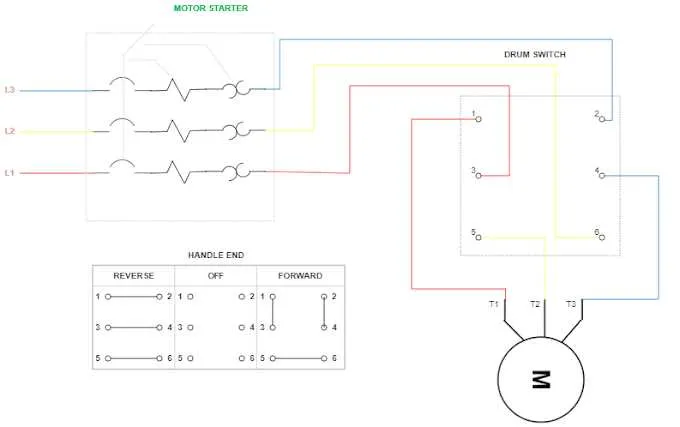
Next step: The changeover switch must be correctly wired to swap the polarity of the current supplied to the engine. This is essential for reversing the direction. Typically, the switch will feature a set of contacts that alternate between providing power in one direction and reversing it to the other. Ensure the switch type matches your setup’s power rating and capacity.
Final checks: Verify all connections and confirm that the system responds correctly when toggling between forward and reverse motions. Any loose connections or improper wiring can lead to inefficient performance or complete failure of the system. Test the circuit with the motor off to ensure proper grounding and safety before activation.
Reversible Electric Machine Connection Setup
For proper installation of a two-directional electric unit, follow these steps to ensure safe and efficient operation:
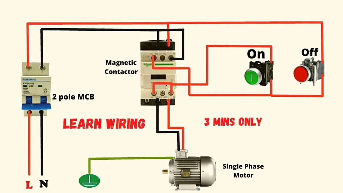
- Connect the power lines: Begin by attaching the supply cables to the terminals of the controller. Ensure the wires are securely tightened to avoid any loose connections.
- Integrate the direction control switch: This switch should be wired between the power source and the machine. It allows switching between forward and reverse operations. The two-position switch typically uses a double-pole double-throw (DPDT) setup for reversing the current flow.
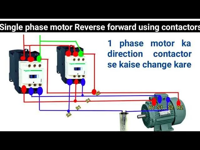
- Verify the capacitor configuration: A starting capacitor should be included for improved efficiency. It helps to initiate motion in either direction. The capacitor is usually connected in series with the winding, ensuring correct phase shift during startup.
- Ensure proper grounding: All components of the system should be grounded to prevent electrical hazards. Verify that the ground wire is attached to the motor housing and the controller unit.
- Check the rotation direction: Before full operation, test the motor in both directions. If the rotation is incorrect, reverse the connections to the windings via the direction switch.
For optimal performance, make sure the control unit is rated appropriately for the voltage and current requirements of the machine. Always follow the manufacturer’s instructions to avoid damaging sensitive components.
How to Identify the Terminals on a Reversible Electric Drive

To correctly identify the terminals on this type of drive, first locate the terminal block where the power connections are made. You will typically find three or four terminals: two for the supply voltage and one or two additional ones for reversing the rotation direction. The terminal labeled “L” is for the live (or hot) connection, and the one marked “N” is for neutral. The other terminals, often marked with “F” or “R”, correspond to the connections that allow reversing the direction. The “F” terminal is for forward direction, and the “R” terminal is for reverse. These markings ensure proper direction control based on the connections made to the control circuit. Make sure to check the manufacturer’s guide for specific terminal configurations as they may vary slightly across different designs.
Step-by-Step Guide to Connecting a Two-Wire Electric Device with Reversible Direction

Start by ensuring the power supply is disconnected. Use a multimeter to confirm that no voltage is present at the terminals where you’ll be working. This is crucial to avoid electrical shocks.
Next, identify the two terminals for input power: one for live and one for neutral. Attach the live wire from the power source to the input terminal marked “L”. Connect the neutral wire to the “N” terminal. These should be secure and tight to avoid any loose connections.
For switching the direction, you’ll need a control switch. This switch will reverse the connection of two wires inside the device. Connect one wire from the switch to the first terminal of the control component (often marked “A”). The other wire from the switch should be connected to the second terminal (marked “B”). These wires should also be securely attached.
The next step is to connect the two output terminals to the respective connectors of the device. Depending on the model, there will typically be two terminals: one for clockwise rotation and the other for counterclockwise. Connect the output wires accordingly, ensuring they are firmly in place. The clockwise terminal is often marked with “CW” and the counterclockwise with “CCW”.
Finally, double-check all connections for accuracy and tightness. When you’re certain everything is properly connected, restore the power and test the control switch. The device should change directions with each press of the switch. If it doesn’t, verify the wiring and ensure the switch is functioning correctly.
Ensure the control switch is rated for the voltage and current required by your setup to avoid overheating or damage. It’s also essential to use high-quality connectors to ensure long-lasting reliability.
Troubleshooting Common Electrical Connection Issues

If the device fails to run in both directions or shows inconsistent behavior, start by checking the power supply. Ensure that the voltage at the terminals matches the rated input and is stable. A fluctuating or insufficient supply can cause malfunction.
Next, inspect the control circuit for continuity. Use a multimeter to verify that the contactors or relays switch correctly, and no connections are broken. A loose connection can prevent the device from reversing or operating at full capacity.
Inspect the reversal switch carefully. If the mechanism isn’t fully engaging or the switch is worn out, it will not properly change the direction. Replace or clean the switch contacts if necessary, and confirm that it correctly aligns with the control system.
Check the capacitor. If it is swollen, leaking, or shows signs of damage, replace it immediately. A failing capacitor can cause the system to run in only one direction or not start at all.
Ensure the motor windings are correctly connected to the circuit. Incorrect connections can result in overheating or poor performance. Use a continuity tester to check the windings for damage or disconnections.
Examine the junction box and terminals for corrosion. Moisture or debris buildup can cause intermittent failures. Clean all terminals and apply appropriate anti-corrosion treatment to prevent further issues.
If the system is running but with reduced efficiency or power, test the current draw. Overcurrent may indicate an overload, while undercurrent suggests insufficient power delivery. Both can point to problems with the connections or a failure within the control system.