For effective installation of a control circuit, it is essential to clearly identify the terminals involved. The configuration typically includes three primary connections: one for input, one for output, and a common connection that serves as the path for the signal. Proper understanding of these connections ensures smooth operation and minimal risk of malfunction.
First Terminal: This terminal is responsible for receiving the input signal, typically from a power source. It is crucial that this connection is well-insulated and securely fixed to avoid any electrical interference.
Second Terminal: This is where the output signal is directed. Ensuring that the output is correctly wired to the device being controlled will prevent short circuits and optimize performance.
Common Terminal: Serving as the reference point, this connection provides a stable baseline for the signal flow. Any disruption here can affect the functionality of the entire system, so regular checks for wear or corrosion are recommended.
Using the proper connection pattern minimizes the chance of miscommunication between components. Always verify the compatibility of the components involved, and check the wiring carefully to ensure everything aligns with the system specifications.
Wiring Setup for a 3-Terminal Control
To properly connect a 3-terminal control, follow these essential steps:
- Terminal 1 (Common): This terminal is used for the incoming power, typically from the power source.
- Terminal 2 (Load): Connect this terminal to the device you intend to control, such as a light or appliance.
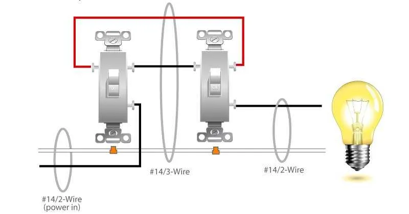
- Terminal 3 (Traveler): This terminal is responsible for sending power between the control and the connected load when switched on.
It’s crucial to ensure the correct polarity when making connections, especially for the traveler wire, as improper wiring can cause malfunction or even damage to the components. Always use high-quality cables that are rated for the required voltage and amperage to prevent overheating and ensure long-lasting operation.
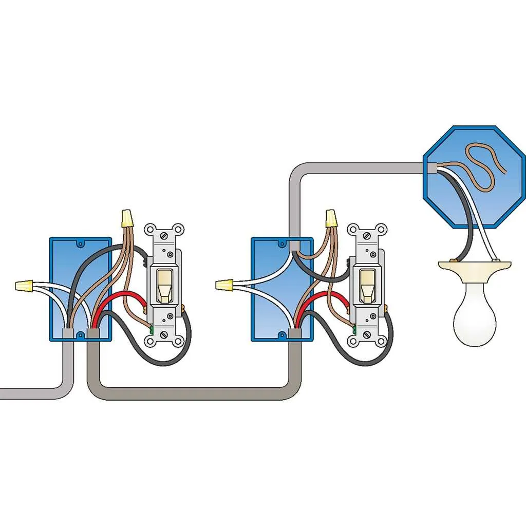
If you’re installing a setup with multiple controllers in series, ensure that each unit has proper connections to handle the current load safely. Use standard color codes to easily distinguish each wire–typically black for hot, white for neutral, and green for ground. However, local electrical codes might vary, so always double-check with them before starting your installation.
How to Connect a Single-Pole Control Using a 3-Wire Setup
To configure a basic on/off control using a 3-conductor setup, first, identify the incoming line that carries current. Connect the black (live) conductor from the power source to the terminal on the first end of the mechanism. The second terminal should be connected to the device (light or appliance) you wish to control. The third conductor serves as the neutral, completing the circuit back to the power panel. Ensure that the grounding conductor is properly attached to the grounding screw for safety.
In this configuration, the live wire directly connects to the controlled unit, while the neutral wire runs back to the power panel, providing the return path. Test the setup before finalizing installation to ensure the system operates correctly, with the mechanism turning the connected appliance on and off as desired.
Understanding the Function of Each Conductor in a Multi-Conductor Circuit Setup

The first conductor in this system serves as the incoming current path. It connects to the power source, typically at the panel. This conductor is often labeled as the “live” or “hot” and carries electricity to the device in question.
The second conductor is responsible for carrying the return current back to the power source. It connects to the load, such as a lamp or fan, and completes the circuit when activated, allowing current to flow freely through the load when needed.
The third conductor functions as a control or switching element. It connects to the control device, and when engaged, it either completes or breaks the circuit depending on the state of the controlling mechanism. This conductor ensures the device can be toggled on or off as required, enabling functional control of the electrical path.
Common Wiring Mistakes in Circuit Connections and How to Avoid Them

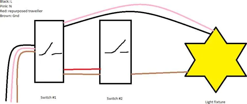
Incorrectly Connecting the Traveler Wires: Always double-check the path of the travelers, as connecting them to the wrong terminals can lead to malfunction. Ensure that one traveler connects to the first terminal and the other to the second terminal of the controlling devices. Misplacing these leads can result in non-functioning setups.
Improper Grounding: Never neglect the grounding process. An ungrounded circuit increases the risk of electric shocks. Make sure all metal components are properly grounded to the system’s main grounding point to prevent potential hazards.
Overlooking Power Source Placement: Ensure that the power source enters the first controlling unit and not directly into the light fixture. Connecting the power source to the wrong location might cause unexpected behavior or total failure of the system.
Mixing Up the Common and Traveler Wires: Mixing up the common wire with a traveler can cause issues where the light doesn’t turn on or off correctly. Identify the common lead clearly before connecting it to the appropriate terminal to prevent this mistake.
Failing to Test the System Before Closing: After making connections, it’s critical to test the circuit before securing everything. Verifying functionality beforehand ensures that any errors are caught and corrected immediately.
Using Incorrect Wire Gauge: Using wires that are too thin can lead to overheating or potential fire hazards. Refer to manufacturer guidelines to determine the correct wire gauge for your specific application.