For a reliable setup of an automatic entry system, ensuring proper connections of all components is essential. Start by examining the power supply, which is typically connected to a circuit that controls both the motor and sensors. Make sure the power source is stable and capable of handling the load to prevent issues with system activation.
Motor Control is one of the primary functions in this setup. The motor should be wired to a relay switch that allows the controller to send signals for opening and closing. The control unit sends the signal to engage the relay, which in turn powers the motor. Ensure all connections are secure and insulated to avoid any short circuits.
Sensor Integration is critical for the safe operation of the system. Typically, sensors are placed along the tracks to detect movement and ensure the system halts if an obstruction is detected. These sensors are usually connected to the controller via low-voltage wiring, ensuring that the signals are transmitted accurately. Check the sensor alignment and connections regularly to avoid malfunctions.
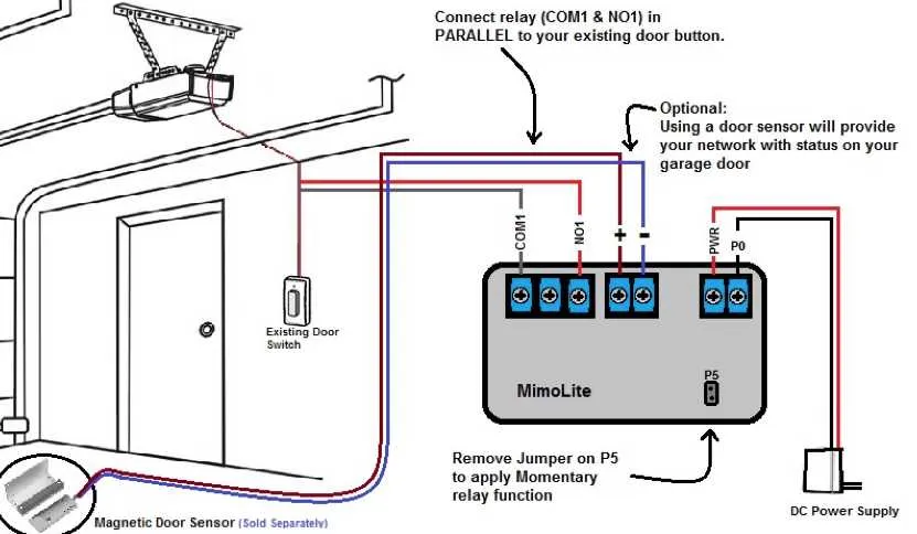
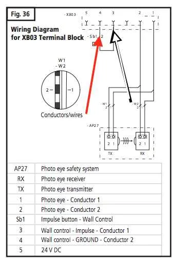
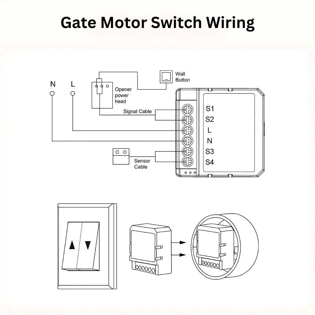
Wiring Setup for Automatic Entry System
To ensure proper functionality, connect the power supply to the motor unit using appropriately rated wires. Use a dedicated circuit with a fuse or circuit breaker rated for the system’s power demand. For safety, ground the unit through the designated terminal, avoiding shared connections with other devices. Ensure that the control panel is wired to the motor with a two-wire system for basic control and a third for safety features like the sensor.
For communication between the user interface and motor unit, use a low-voltage wire. A 24V system is commonly used, but verify the specifications of the unit for compatibility. For the safety sensors, ensure that the wires are properly insulated and do not interfere with moving parts. Place the signal cables as far as possible from the power supply to reduce electromagnetic interference.
Test all connections before powering the system. Check for continuity and proper insulation, particularly in the low-voltage circuits. If the setup includes a remote control, verify the signal reception and transmission. Adjust the wiring for optimal response and ensure that all components are securely mounted and accessible for future maintenance.
Understanding the Wiring Layout for Automated Entry Systems

Start by ensuring the power is turned off before beginning any wiring task. Safety is crucial, as improper connections can lead to malfunctions or hazards.
- Identify the terminal blocks on the control panel where the main power input connects. Typically, the neutral and live wires should be placed into these terminals.
- Connect the sensors’ wiring to the appropriate terminals. These sensors control the opening and closing mechanism and must be wired correctly to ensure functionality.
- The motor terminals should be carefully matched with the corresponding leads from the motor. These are often color-coded to help with proper connection.
- Install the safety features, such as the reverse system or limit switches. These should also be wired to the control panel with the correct polarity to function properly.
Make sure to follow the manufacturer’s wiring guide to prevent incorrect connections. Miswiring can cause the system to behave erratically or fail to operate.
- For dual-button control panels, connect each wire to its designated terminal. One button typically operates the opening function, while the other controls the closing.
- Wire the power supply to the appropriate fuse or breaker to ensure the system is protected from overloads. This prevents short circuits or fires.
After completing the connections, double-check all wiring before restoring power. Test the system to verify all components function as expected. Troubleshooting wiring issues can often involve checking for loose connections, broken wires, or incompatible components.
Common Connections in Motorized Entry System Circuits
When wiring an automatic entry system, ensure proper connections to power, control, and safety components. First, connect the power supply to the system’s main terminal block, typically using a 120V or 240V line, depending on the model specifications. The neutral and ground wires must also be securely connected to their respective terminals to prevent malfunctions and ensure user safety.
Next, ensure the motor leads are wired to the terminal that controls its operation. Typically, the system includes two motor terminals: one for forward and the other for reverse movement. These terminals control the direction of movement and require a switching relay to alternate between them based on the user input from the remote control or wall switch.
The control board must be connected to sensors that detect obstructions or potential malfunctions. This connection is crucial for reversing the movement of the system when a blockage is detected. A common safety feature is the photo-eye sensor, which must be wired to the control board for proper functionality. It should be positioned and aligned according to manufacturer instructions to avoid false readings.
Additionally, the wall-mounted control switch must be connected to the system’s controller. This switch will send a signal to the motor’s control circuit to activate or deactivate the operation. Ensure the switch’s wiring corresponds to the correct terminals on the control panel, preventing damage to the system during operation.
For wireless remotes, the transmitter needs to be programmed into the receiver unit, often located within the system’s control panel. Ensure that the programming follows the specific steps outlined by the manufacturer to ensure seamless operation.
Lastly, check for any auxiliary features, such as lights or security features, which may require their own separate wiring to the control system. These components often include simple relay or switch connections that should be correctly configured to function during the opening or closing cycle.
Troubleshooting Power Issues in Motorized Systems

Check the power supply first. Ensure the unit is plugged into a working outlet. Test the socket with another device to confirm it’s functional. If there’s no power, inspect the circuit breaker and reset it if necessary.
Examine the fuse. If it has blown, replace it with the correct type and rating specified in the manual. A blown fuse can often be a sign of a surge or overload. Be sure to address any underlying issues before replacing the fuse.
Verify the wiring connections. Loose or corroded wires may cause intermittent power loss or prevent the system from starting. Tighten all connections and clean any corroded terminals.
If the system is not responding despite power being present, the control board may be malfunctioning. Inspect it for burnt components or visible damage. If damaged, replacing the board may be necessary.
Test the remote or wall control unit. A dead battery in the remote or a faulty switch in the control panel could prevent the system from operating. Replace the battery and check the function of the switches.
Lastly, check the capacitor. If the motor isn’t starting or is making strange noises, the capacitor may be faulty. Test it with a multimeter and replace if it fails to hold charge or shows signs of damage.