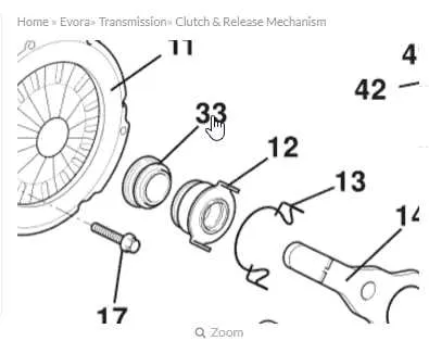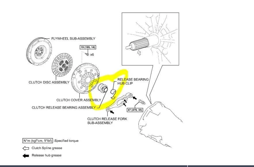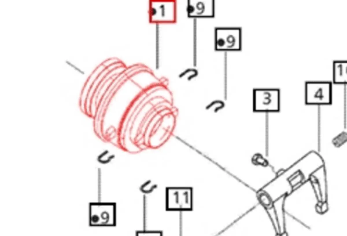
For accurate maintenance and assembly of a clutch release system, it’s crucial to understand the layout of the pressure plate, release fork, and related components. The correct orientation and placement of these parts ensure smooth engagement and disengagement during shifting.
Key components: The diagram should clearly mark the clutch diaphragm spring, release bearing, and the fork arm, showing how these elements interact with the flywheel and pressure plate. Pay close attention to the clearances between the release mechanism and the clutch diaphragm to avoid excessive wear.
Proper alignment of the release fork with the bearing is essential for preventing uneven pressure distribution, which can lead to premature failure. Always check the bearing surface for signs of damage, as any imperfection can cause significant friction during operation.
Ensure that the correct force is applied when assembling these parts. Over-tightening or under-tightening can distort the components, affecting performance and durability. For a long-lasting system, regular inspection and timely replacement of worn elements are highly recommended.
Clutch Release Mechanism Overview

When replacing or maintaining a clutch, understanding the setup of the release component is critical. The primary function of this part is to engage and disengage the clutch mechanism, allowing smooth gear shifts. The release unit typically includes a few essential elements: the sleeve, fork, and pressure spring. These parts work together to transfer force from the pedal to the clutch assembly. Incorrect installation or misalignment of the parts can lead to poor pedal response or premature wear.
Ensure that the release assembly is properly aligned with the fork and sleeve during installation. Any deviation from the correct positioning may cause excessive friction, leading to overheating and failure. Regular inspection of these components, especially for wear or damage, is important for maintaining optimal clutch performance.
For optimal function, it’s essential to check the clearance between the fork and the pressure plate. The correct spacing allows smooth engagement and disengagement. If the clearance is too tight or too loose, it can affect pedal feel and the overall longevity of the system.
Additionally, always use high-quality lubricants where necessary to reduce friction and prevent rust, particularly around the fork and sleeve contact areas. Inadequate lubrication can cause wear and reduce the lifespan of the system, leading to costly repairs.
By maintaining these key aspects, you’ll ensure a more reliable and long-lasting clutch system. Consistent checks and proper maintenance reduce the chances of failure and improve driving performance.
How to Read a Clutch Release Mechanism Schematic for Manual Transmissions

Start by identifying the key components: the pressure plate, clutch fork, release bearing, and flywheel. These parts will be represented by simple shapes or symbols. The schematic often indicates the movement of the release fork, showing how it interacts with the pressure plate. Understand the direction of motion: typically, a horizontal line or arrow represents the travel direction of the release system when the clutch pedal is engaged.
Look for the pivot points. The clutch fork’s hinge is crucial for determining how force is applied to the release mechanism. If the diagram includes the movement of hydraulic or mechanical linkages, follow the flow paths or arrows to see how pressure from the pedal is transmitted to the clutch assembly.
Focus on the interaction between the release bearing and the pressure plate. The release bearing should be shown making contact with the fingers of the pressure plate when engaged, creating a disengagement force. The diagram should also show the clearance between the bearing and the pressure plate when the pedal is not pressed.
Review any additional notes or annotations, as these can explain specific tolerances or installation details that are crucial for proper function. Pay attention to any labeled angles or specific distances between components, as they can affect the engagement or disengagement of the clutch.
Once you’ve familiarized yourself with the key elements, cross-reference with the transmission manual for specific assembly instructions or troubleshooting tips. Understanding the diagram allows you to identify if a part is misaligned or malfunctioning within the clutch mechanism.
Common Types of Clutch Release Bearings and Their Structural Variations
When selecting a clutch release component, it’s important to understand the different types and how their designs impact performance. Below are the most common variants and their structural differences.
- Ball Bearing Type: Features a series of steel balls housed in a race. Ideal for high-speed applications, providing smooth disengagement.
- Roller Bearing Type: Uses cylindrical rollers instead of balls, offering increased load-bearing capacity. This type is suitable for heavy-duty vehicles.
- Carbon Type: Made with carbon composite materials for enhanced durability. Often used in high-performance or racing applications where heat resistance is critical.
- Needle Bearing Type: Consists of long, thin needles that provide greater surface contact, reducing wear in high-torque environments.
Each type varies in size, material composition, and the number of components involved, affecting their lifespan and suitability for different vehicles and driving conditions. The correct choice depends on load requirements, vehicle specifications, and expected performance needs. Always consult a vehicle’s manual or a professional mechanic for guidance on the appropriate selection.
Identifying Wear and Tear Through Clutch Release Mechanism Schematics
Examine the clutch release system to spot wear patterns, paying attention to surface degradation, cracks, or discoloration. If the pressure plate or fork shows signs of uneven wear, it may indicate that the contact surface is misaligned or that components are functioning improperly. Check for irregularities in the movement path and the alignment of the mechanism, as this can affect the overall lifespan.
Look for signs of heat damage, such as burnt or scorched areas, which suggest excessive friction. This can result from improper adjustment or a failure in the lubrication system. If the contact points between the release component and the clutch assembly appear excessively worn, consider replacing them before further damage occurs.
When interpreting schematics, focus on areas prone to frequent contact and stress. Wear patterns near pivot points or areas subjected to high force are key indicators of potential failure. Keep track of these spots in the diagram to predict when maintenance or replacement will be needed.