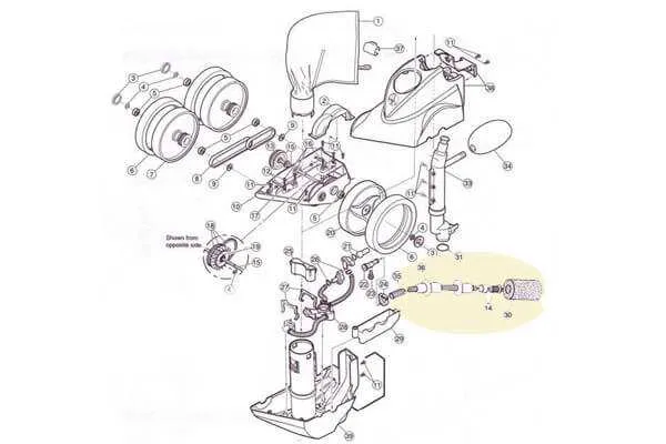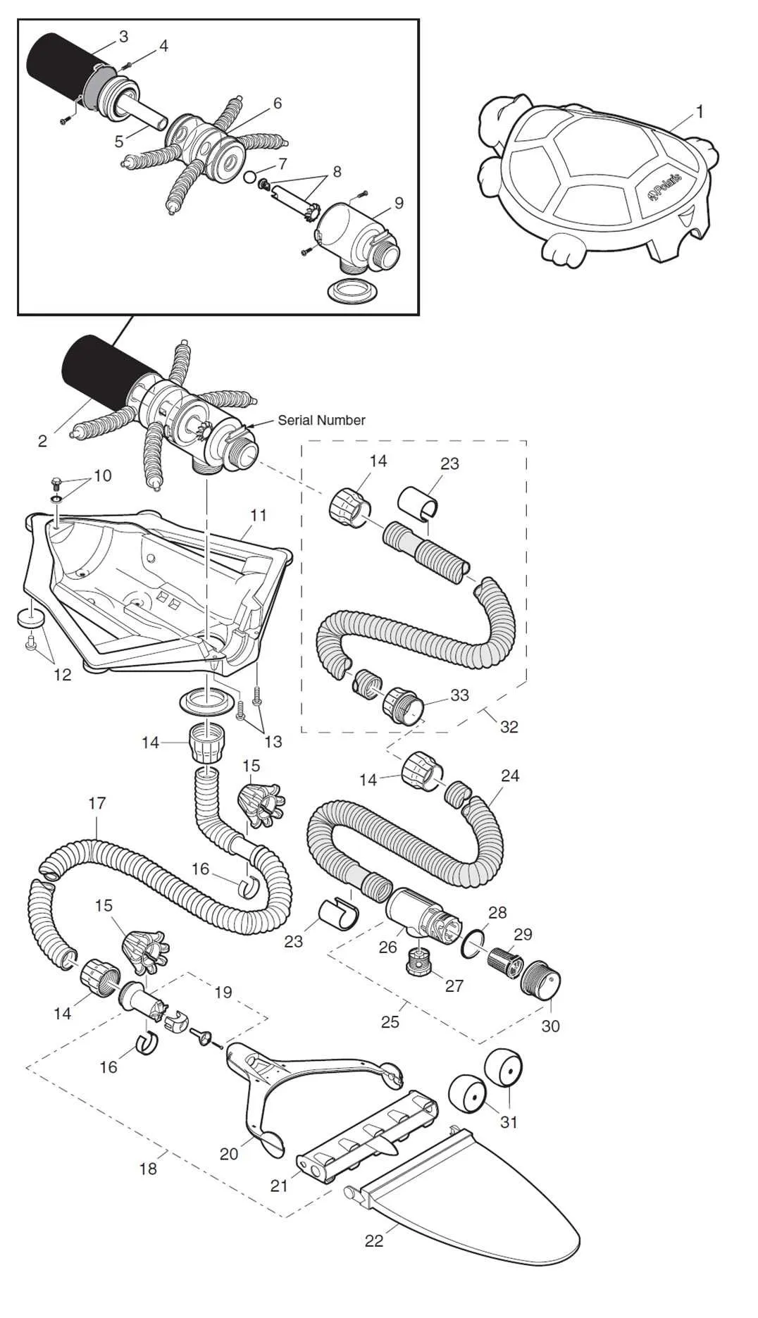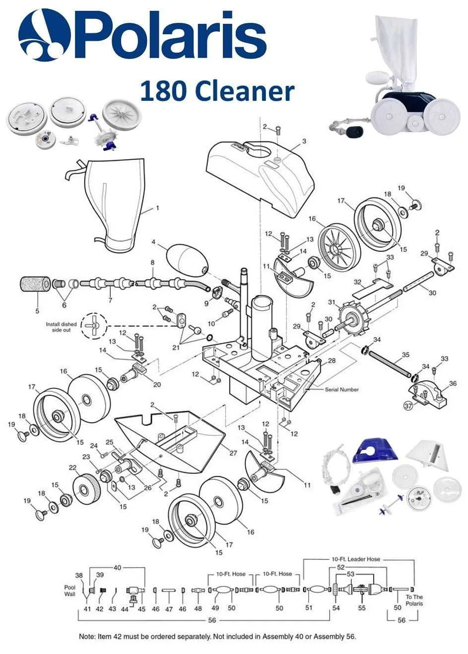
To ensure the optimal functioning of your robotic pool cleaner, it is essential to understand the exact configuration and structure of its internal components. Identifying and replacing worn-out or damaged parts is crucial for extending the lifespan of your cleaner. Start by examining the key sections of the cleaning unit, such as the drive mechanism, filtration system, and the scrubbers that remove debris from pool surfaces.
Refer to a detailed schematic of the cleaner to locate each element. This will help you quickly identify which parts need attention, such as the belts, wheels, or brushes. Knowing the layout allows for precise troubleshooting, making repairs simpler and more cost-effective.
Regular maintenance includes checking the motor, hoses, and any moving joints. Over time, parts such as the filtration bag or the wheels may wear down, requiring replacements. When dealing with these parts, always choose high-quality, compatible components for reliable performance. If you’re uncertain about any part’s condition, a visual inspection combined with a schematic will guide you in pinpointing issues efficiently.
By referring to these diagrams and following the recommended guidelines for each section, you’ll avoid unnecessary downtime and keep your cleaner running at peak efficiency throughout the swimming season.
Detailed Breakdown of the Components
For effective maintenance or repair of the robotic pool cleaner, start by locating the specific section of the unit you need to address. Begin with the drive mechanism, which includes wheels, belts, and gears. These components ensure smooth movement across the pool floor. Regular inspection of the belts for wear and tear is crucial to avoid malfunction.
The motor housing, which contains the internal electrical components, is essential for power distribution. Ensure that seals around the housing are intact to prevent water damage. Pay close attention to the intake and exhaust ports, as blockages here can reduce performance.
Next, the filtration system, including the baskets and filters, should be cleaned frequently. Clogs can impair suction and reduce the efficiency of debris collection. It is recommended to replace filters when they show signs of damage or reduced capacity.
In the event of a malfunction, check the flow valves and the swivel mechanism for signs of wear. These parts control the cleaner’s direction and are critical for its mobility. If either component is damaged, it could cause erratic behavior, necessitating immediate replacement.
Lastly, examine the cord and cable assembly for any fraying or kinks, which can limit the range of movement and power supply to the cleaner. Regularly untangle and inspect for any visible damage to ensure the system runs smoothly.
Identifying Key Components in the Diagram
Start by locating the main drive unit, which is typically represented at the center of the schematic. This part connects to the motor and is responsible for powering the system’s movement. Pay close attention to the bearings and seals that surround this unit, as they ensure proper functioning and prevent water leakage.
Next, identify the propulsion system components, such as the fins or wheels. These parts are critical for forward motion and often have unique markings indicating their orientation and size. They are typically linked directly to the drive unit and require accurate alignment for optimal performance.
The filtration system, including pumps and filters, is usually placed near the edges of the visual. These parts are essential for water circulation and debris collection. Look for the inlet and outlet ports, as they show the flow direction and connection points for hoses.
Don’t overlook the control module and sensor components. These small but vital units are typically indicated with electrical symbols and help monitor the system’s operation. They can include pressure sensors, temperature gauges, or flow meters that help adjust the machine’s behavior based on environmental factors.
Lastly, examine the frame and structural components. These parts are often reinforced for durability and provide stability to the entire assembly. Check for any pivot points, such as hinges or joints, that allow for movement or adjustment.
How to Use the Polaris 280 Parts Diagram for Troubleshooting

To resolve issues effectively, begin by identifying the exact location of the malfunction. The schematic layout offers a comprehensive view of key components and their connections, which is crucial for pinpointing the source of problems.
Follow these steps to troubleshoot efficiently:
- Inspect Key Components: Start by locating the motor, pumps, and other core parts on the blueprint. Verify their condition, ensuring no visible damage or wear.
- Check Connections: Look for any loose wires or tubes. The visual representation helps in understanding how parts are interconnected, which can reveal poor connections or leaks.
- Verify Orientation: Ensure that rotating parts and valves are correctly aligned. The schematic will show their orientation and installation sequence, which is critical for proper function.
- Cross-reference with the Manual: Compare the part numbers and references in the schematic with the user manual to confirm compatibility and ensure no parts are missing or incorrectly installed.
- Test Moving Parts: Utilize the diagram to check the movement and flow of the equipment. Troubleshoot by focusing on areas where irregular motion or blockages may occur.
By cross-referencing components on the layout, you can systematically rule out areas that are functioning correctly and isolate the issue quickly, ensuring a faster resolution to mechanical faults.
Step-by-Step Guide to Replacing Components Based on the Diagram

Begin by ensuring the pool cleaner is completely powered off. Disconnect it from the power supply to avoid any risk of electric shock.
Examine the reference schematic to identify the worn-out or damaged parts. Most common issues include worn wheels, clogged filters, and malfunctioning drive belts. Each part is numbered for quick identification in the chart.
Start with the drive mechanism. If the motor belt is loose or snapped, remove the access cover and detach the old belt. Replace it with a new one of the same specifications, making sure it is tightly secured but not overly strained.
Next, inspect the wheels. If they are no longer rotating smoothly, remove the fasteners holding them in place. Replace the wheels with identical models, ensuring they click into place and rotate freely without obstruction.
Clean or replace the filter depending on the condition. Detach the filter compartment, remove any debris, and replace the filter if it appears worn or clogged. Ensure the new filter fits snugly and seals properly to prevent leaks.
If the cleaner is not moving in a straight line or if it gets stuck, check the hoses and swivels. Replace any worn swivels that might be causing binding. Inspect the hose for cracks and replace it if necessary.
Once all parts are replaced, reassemble the unit carefully, referring to the schematic for the correct orientation of each component. Ensure that all screws and fasteners are tightened securely.
Test the cleaner in a controlled environment to confirm that all parts are functioning properly before full operation. If there are still issues, double-check the assembly and ensure all connections are correctly aligned.