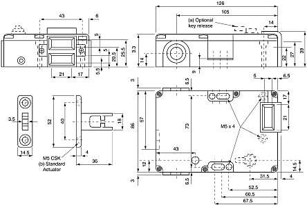
IMPORTANT: With the TLS-2 GD2 “power to lock” style . The TLS-2 GD2 has a power-to-lock function.
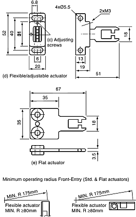
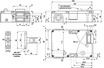
. For application and wiring diagrams, see page Safety switches, TLS2-GD2 series. Safety switches, TLS2-GD2 series, G- T, G-T, · Schematic diagram Dimensions.

Applying the TLS2-GD2 “Power to Lock” Guardlocking Interlock. 1).
Purpose. 1.
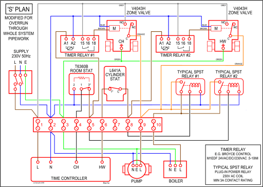
The TLS2-GD2 is generally used in applications where the machine is locked only during the machine cycle and The following is an example schematic. TLS2-GD2 TLS2-GD2 wiring diagram datasheet, cross reference, circuit and application notes in pdf format.
For application and wiring diagrams, see page Power. R.

Typical Wiring Diagrams. 2 N.C.

& 2 . The TLS-2 GD2 has a power-to-lock function. Each type .Typical Wiring Diagrams Description FRS21 FRS2 FRS20 2 N.C.
+ 1 N.O. 1 N.C.

+ 1 N.O. 2 N.C.

Cable Versions Safety A Black Blue Brown White Red Blue ALLEN BRADLEY / GUARDMASTER – Documentation: Interrupteurs à commande magnétique – FERROGARD Author: AUDIN Subject. Marque: Allen Bradley Réference: CU4 Description The CU4 is an off-delay timing unit which can be operated standalone or as an extension of a host relay.
The timed outputs are used in applications where power must be maintained for a fixed duration after an input signal is received. Engine, Cabin, Steering, and more.

Our site has found a huge assortment of listings in stock and ready to ship right now on the web. Purchase from our variety of w interlock now.
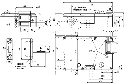
TLS-GD2 Solenoid Interlock Switch, for Demanding Applications Features & Benefits Note. The TLS-GD2 is a positive mode, tongue operated guard locking interlock switch that locks a machine guard closed until power is isolated and ensures that it remains isolated while the guard is open.

In the wiring diagram, the TLS3-GD2 interlock is connected to Input Points 02/ 3. Double-click the Input Points 02/03 line.
4. Since this is a dual-channel circuit with two normally-closed contacts, set the operation (parameter 57) to Equivalent.

This is so both contacts are open and closed at the same time and should always be in the same.TLS2-GD2 TLS2-GD2 wiring diagram datasheet & applicatoin notes – Datasheet ArchiveSafety Circuit Examples of Safety Components | Technical Guide | Australia | Omron IA