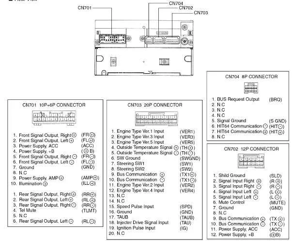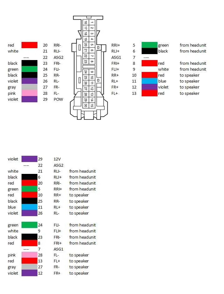
If you’re replacing or installing a new sound system, it’s crucial to understand the pinout configuration of your vehicle’s audio system. The wiring setup for the power, speakers, and ground connections must be correctly aligned to avoid potential damage and ensure proper functionality. Use this detailed guide to identify and connect the necessary terminals in your setup.
Power Supply: The most critical element is the constant 12V power input. Locate the wire that provides steady voltage to your stereo unit. This will ensure that your system retains memory settings, such as station presets, even when the ignition is turned off.
Speaker Connections: Depending on your setup, the audio output wires should be correctly matched with the speaker inputs. Typically, these include two for the front speakers (left and right) and two for the rear. Be sure to check that polarity matches for both the positive and negative terminals to avoid phase issues in sound quality.
Grounding: The grounding wire should be securely connected to a clean, unpainted metal part of the vehicle’s frame. A poor ground connection is one of the most common causes of electrical interference or malfunction, so ensure this step is thoroughly checked.
Once all connections are securely made, double-check that each wire is well-insulated and free from any potential short circuit hazards. This simple precaution can prevent damage to your new stereo system and keep your setup running smoothly.
Wiring Connections for Car Audio System
For a smooth and safe installation, ensure to connect the power and ground wires to their respective terminals. The red wire should be linked to the constant power supply, while the black wire must go to a solid ground point to avoid electrical faults.
Speaker wires should be connected with color-coded precision: the front left is typically marked with a white or white with black stripe, while the front right is often represented by a gray or gray with black stripe. Rear speakers follow a similar color code, with the rear left being green and the rear right marked by purple.
To properly connect the antenna wire, ensure that it is secured to the corresponding terminal, allowing for optimal reception. Additionally, check the ignition wire (often blue or yellow), as it controls the unit’s power when the vehicle is turned on or off.
For aftermarket integration, using an ISO adapter harness can simplify the process, ensuring compatibility between the new system and the existing wiring structure without cutting factory wires.
Always double-check connections before powering up the system to avoid shorts or damage to the components.
Understanding Pinouts and Color Codes for Toyota Audio Systems

For proper installation or troubleshooting of the sound system in your vehicle, understanding the pin configuration and associated color codes is crucial. Each connection plays a vital role in ensuring that the system operates optimally. Pay close attention to the following common color codes and pin assignments.
Power Connections: The constant power (usually colored yellow) provides the necessary energy to retain settings when the vehicle is off. The accessory power (typically red) activates the system when the ignition is turned on.
Ground: The ground wire, often black or brown, is essential for completing the circuit and preventing electrical interference.
Speakers: Speaker connections are typically represented by a pair of wires: one for the positive and the other for the negative terminal. These are often color-coded as follows: front left (white and white/black), front right (gray and gray/black), rear left (green and green/black), and rear right (purple and purple/black).
Illumination: The wire for lighting is commonly orange, enabling the dimming of the display when the headlights are on. This allows for better visibility of the system at night.
Amplifier: If an external amplifier is present, it is typically connected to a blue or blue/white wire. This wire triggers the amp to power on when the system is in use.
Antennas: The wire for the antenna is often marked as blue, providing the necessary signal to the antenna for radio reception.
Always cross-check the pinout and ensure each connection is secure and correctly positioned to prevent malfunction. Proper handling of these wires ensures your system operates efficiently without risk of damage or improper function.
How to Properly Connect Power and Ground Wires
To ensure a stable power source, the red wire should be linked to the vehicle’s ignition switch or a fuse that supplies power when the engine is on. This guarantees that your device activates only when the engine starts. For constant power, connect the yellow wire to a direct battery source, ensuring the system retains memory settings when turned off.
The black wire serves as the ground connection. It must be securely fastened to a clean, unpainted metal surface within the vehicle. Use a grounding screw or a bolt that connects to the chassis for proper grounding. Avoid using painted or rusted areas, as poor contact can lead to system malfunctions.
Check the connections with a multimeter to confirm a steady 12V DC power supply before finalizing the setup. Improper connections may result in short circuits, causing potential damage or malfunction.
Troubleshooting Common Issues in Electrical Connections

If you’re experiencing problems with the audio system not powering on or inconsistent sound quality, start by checking the power supply connections. Ensure that all power wires are securely connected, particularly the red and yellow wires. If there’s no power, inspect the fuse for damage or replacement needs.
- Power Failure: Confirm the yellow wire (memory) is receiving power when the ignition is off, and the red wire (12V) when the ignition is on.
- Distorted Sound: Verify the ground wire is properly connected to the vehicle’s metal chassis to prevent interference.
- No Signal: If you’re not getting any sound output, check the speaker connections. Ensure they are firmly attached to the corresponding terminals.
Next, verify the antenna connection to ensure proper signal reception. Loose or disconnected antenna wires can lead to weak or no reception.
- Intermittent Reception: Examine the antenna wire for any visible damage or corrosion at the connection point.
- Static Noise: Inspect the antenna’s grounding to ensure the connection is intact and corrosion-free.
If issues persist, check for any frayed or worn-out wires causing shorts. Damaged wires can lead to malfunctioning components or even complete system failure.
- Short Circuits: Inspect the insulation of wires connected to the system for wear and tear, replacing any damaged sections.
Finally, always double-check the compatibility of the connection harness. Mismatched connectors or adapters can prevent proper functionality.