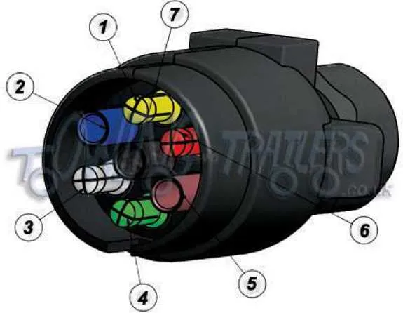
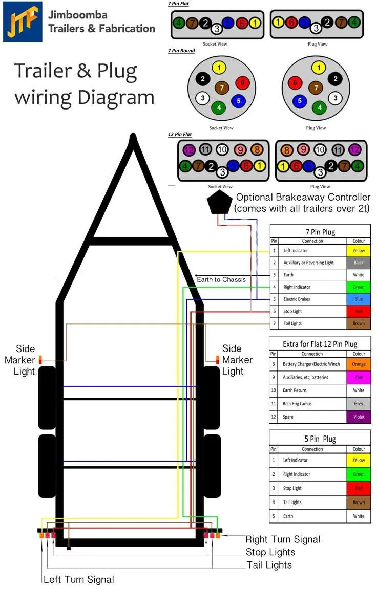
Always match wire color to function, not position. The most common layout includes: brown for tail lamps, yellow for left turn/brake, green for right turn/brake, white as ground, blue for electric brakes, red or black for auxiliary power, and purple for reverse lights. Deviations exist–verify with a multimeter before connecting.
Center terminal is usually reverse lights or auxiliary. When retrofitting or troubleshooting, confirm center contact use. In many setups, it’s left unused; in others, it’s essential for powering interior lighting or backup signals.
Connections should be weather-sealed. Use heat-shrink butt connectors or weatherproof junction boxes to prevent corrosion. Apply dielectric grease inside the socket to improve conductivity and resist moisture.
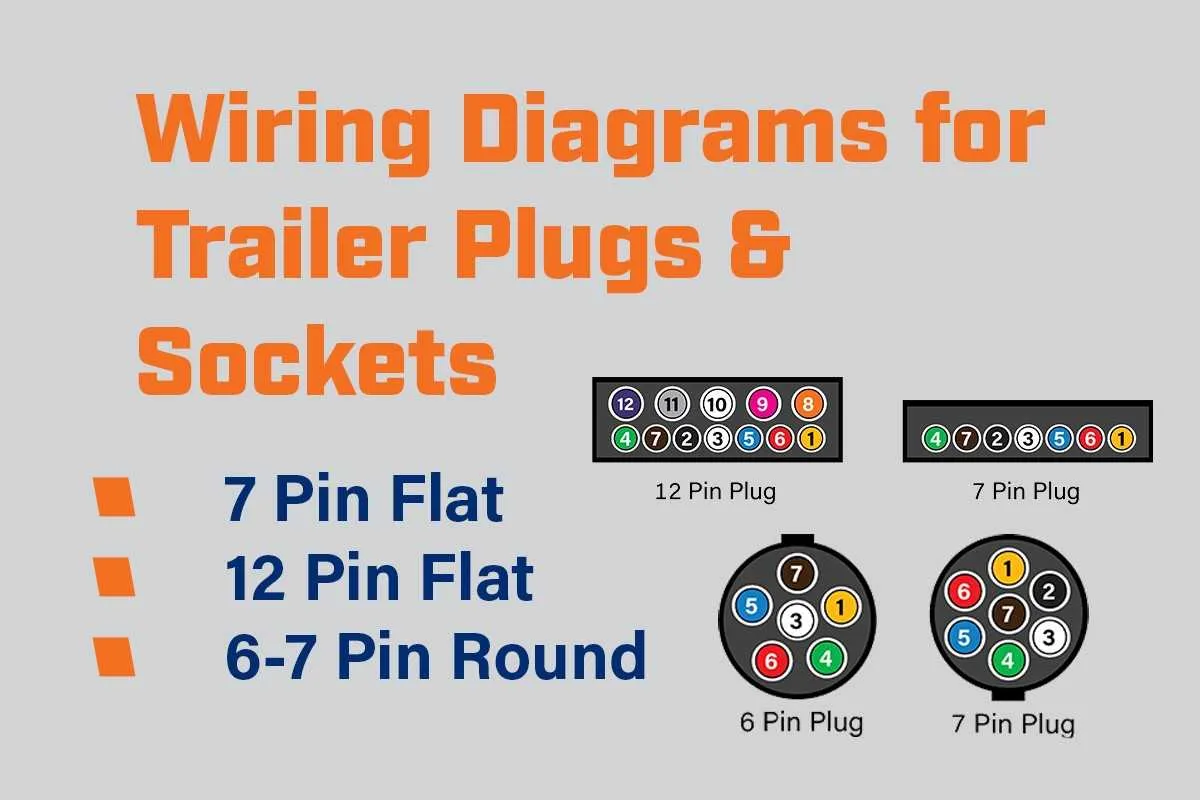
Standard blade-style sockets follow a clockwise pattern when viewed from the front. Numbering starts at the top and proceeds in order: ground, electric brakes, tail/running lights, left turn/stop, right turn/stop, battery charge, and reverse or center auxiliary. Improper placement causes malfunction or safety hazards.
Trailer 7 Pin Wiring Diagram
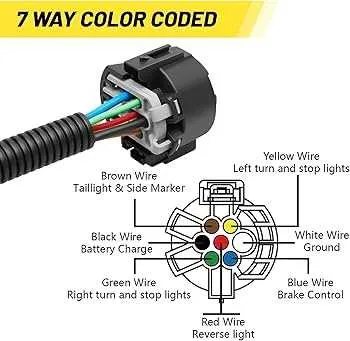
Always connect the ground to the white conductor–this serves as the return path for all circuits. Without a proper earth, lights and brakes may malfunction.
Brown is assigned to the right rear marker and signal illumination. Ensure a solid connection to avoid flickering indicators during travel.
Yellow manages the left directional lamp. Verify this route with a multimeter before finalizing connections.
Green activates the starboard-side flasher. Secure all terminals with dielectric grease to resist corrosion.
Red typically energizes the electric brake system. Route this line through a fuse or circuit breaker rated for the brake controller’s output.
Blue often handles auxiliary functions like reverse lamps or charging systems. Confirm compatibility with towing vehicle output before use.
Black delivers 12V auxiliary power. Use a minimum of 10-gauge copper for this feed to handle higher current demands, especially for battery charging.
Cross-check each wire with a continuity tester before coupling to avoid reverse polarity or inactive circuits.
Understanding the Function of Each Wire in a 7 Pin Connector
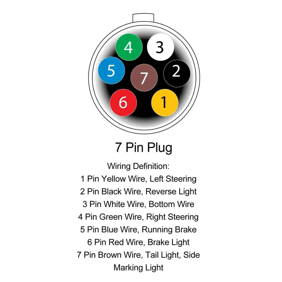
Always match each conductor by function, not just color, to avoid short circuits or signal failure. The brown line typically controls tail and side marker lights, activated when headlights are on. Ensure it’s connected to a fused output from the lighting system.
The yellow strand operates the left turn signal and flashing warning lights. Verify that it’s linked to a dedicated turn relay to prevent overload. On the opposite side, the green conductor controls the right turn indicators with the same setup.
The white cable serves as the primary ground. It must be securely attached to a clean, unpainted metal surface near the front of the chassis. Corroded or loose grounding is the most common cause of electrical issues.
The blue wire activates the electric brake system. It should be routed through a brake controller unit that modulates voltage based on vehicle deceleration. Skipping this controller risks lockup or brake fade.
The red (or black) lead provides auxiliary 12V power, often used to maintain a battery charge or operate internal accessories. This feed must include an inline fuse rated between 20–40 amps, depending on the load.
The purple channel controls reverse lighting. Connect it to the vehicle’s reverse gear circuit only if backup lamps are required by law or for visibility in tight spaces.
Step-by-Step Guide to Wiring a 7 Pin Trailer Plug
Start by disconnecting the vehicle battery to prevent accidental shorts. Use a multimeter to verify circuits before connecting each lead.
- Ground (White): Attach the white conductor to the chassis near the socket mount. Scrape paint for a solid metal contact and secure it with a self-tapping screw or bolt.
- Left Turn (Yellow): Connect to the vehicle’s left indicator circuit. Confirm function with the turn signal activated.
- Right Turn (Green): Link to the starboard indicator. Ensure no cross-feedback from other lighting elements.
- Tail Lamps (Brown): Wire to the vehicle’s parking or running lights. Avoid connecting to brake or indicator lines.
- Brake Lamps (Red): Splice into the dedicated stoplight signal, not combined with turn signals on older systems.
- Auxiliary Power (Black): Feed directly from the battery through a fused 12V source, typically 20A, for internal lights or charging circuits.
- Reverse Lights (Blue or Purple): Optional; attach only if your tow vehicle supports rear illumination triggers.
Secure all joints with weatherproof connectors. Use heat-shrink tubing and electrical tape to seal against moisture. Route all lines away from moving parts and hot surfaces. Verify functionality with a light tester or test lamp before reconnecting the battery.
Troubleshooting Common Issues with 7 Connector Electrical Systems
Start by checking ground continuity. A corroded or loose ground connection is the most frequent cause of malfunctioning tail lights or intermittent brake lamps. Use a multimeter to verify resistance between the negative terminal and the vehicle frame; it should be close to zero ohms.
If turn signals fail on one side, inspect the corresponding contact point in the plug for oxidation or debris. Clean using electrical contact cleaner and a small wire brush. Check for voltage at the socket with a probe while the signal is active; it should read 12V.
When running lights are nonfunctional, test the auxiliary line fuse in the tow vehicle’s junction box. Replace any blown fuses with the exact amperage rating. Also, inspect the insulation on the related conductor for signs of abrasion or melting.
For electric brake problems, measure voltage on the blue wire when the pedal is pressed–expect between 12-14V depending on gain settings. If there’s no output, inspect the brake controller’s internal fuse or check its ground.
Constant battery drain may indicate a short in the charge feed line. Disconnect the plug and measure voltage at the 12V power blade; it should only be live when the ignition is on (unless hardwired). Install a relay or diode isolator if backfeed is detected.
Always secure connectors with dielectric grease after cleaning to prevent moisture intrusion and prolong contact life.