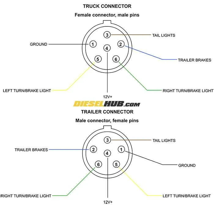
For proper operation of your vehicle and trailer’s electrical functions, the right connections are crucial. Ensuring secure communication between the towing vehicle and the attached load is essential to maintain proper braking and lighting systems.
Start by understanding the purpose of each wire and its role in the overall electrical setup. Each connection serves a distinct function, from providing power to the brake lights to activating the turn signals. This organized approach guarantees safe towing and prevents system malfunctions.
For optimal performance, use a quality connector that matches your towing vehicle’s socket and securely attaches to the corresponding system on the trailer. Be sure to regularly inspect connections for corrosion or wear and replace faulty components promptly.
Key points to remember: Ensure correct polarity when connecting wires to avoid malfunctioning. Always check compatibility with your vehicle’s output and follow standard guidelines for wiring installations. If in doubt, consult an expert to avoid potential risks.
Reliable connections ensure that every aspect of your setup functions as intended, making your travels safer and more efficient.
Understanding 7-Wire System for Towing Vehicles
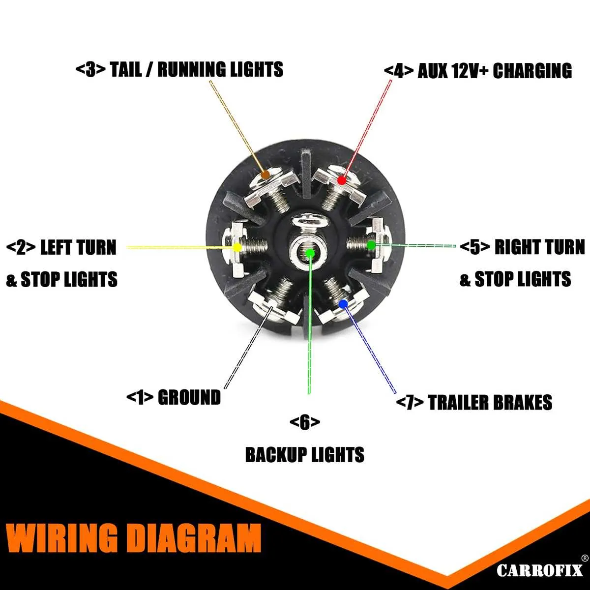
For a reliable connection, follow this color code for a 7-wire configuration: white for ground, brown for running lights, yellow for left turn, green for right turn, blue for the electric system, and purple or black for reverse or auxiliary power. Ensure proper insulation and weatherproofing for all connections to avoid corrosion or short circuits.
Use a high-quality connector and ensure it is tightly secured to prevent any loosening during transit. Be aware that some systems include a battery charge wire; this is typically purple or black. If your system does not include this, make sure to integrate a power feed from the vehicle’s battery for auxiliary or reverse functionality.
Each wire should be checked for continuity before installation, and make sure that there is no slack that could cause wear on the insulation. Also, avoid overloading individual circuits. For the electric system, verify voltage levels to ensure they align with the trailer’s requirements for optimal performance.
Understanding the 7 Pin Connector and Its Electrical Functions
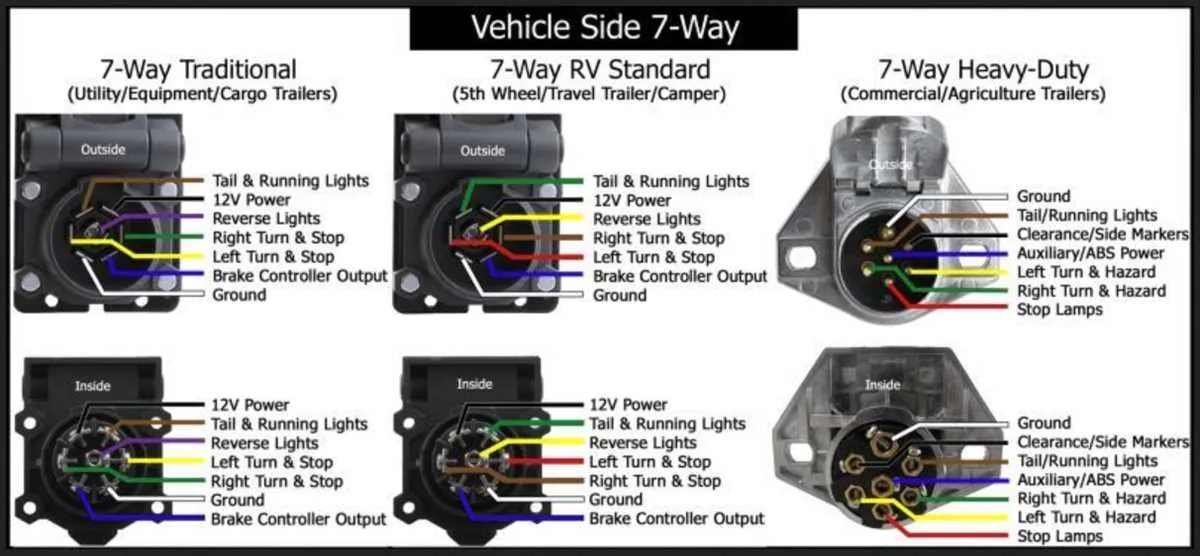
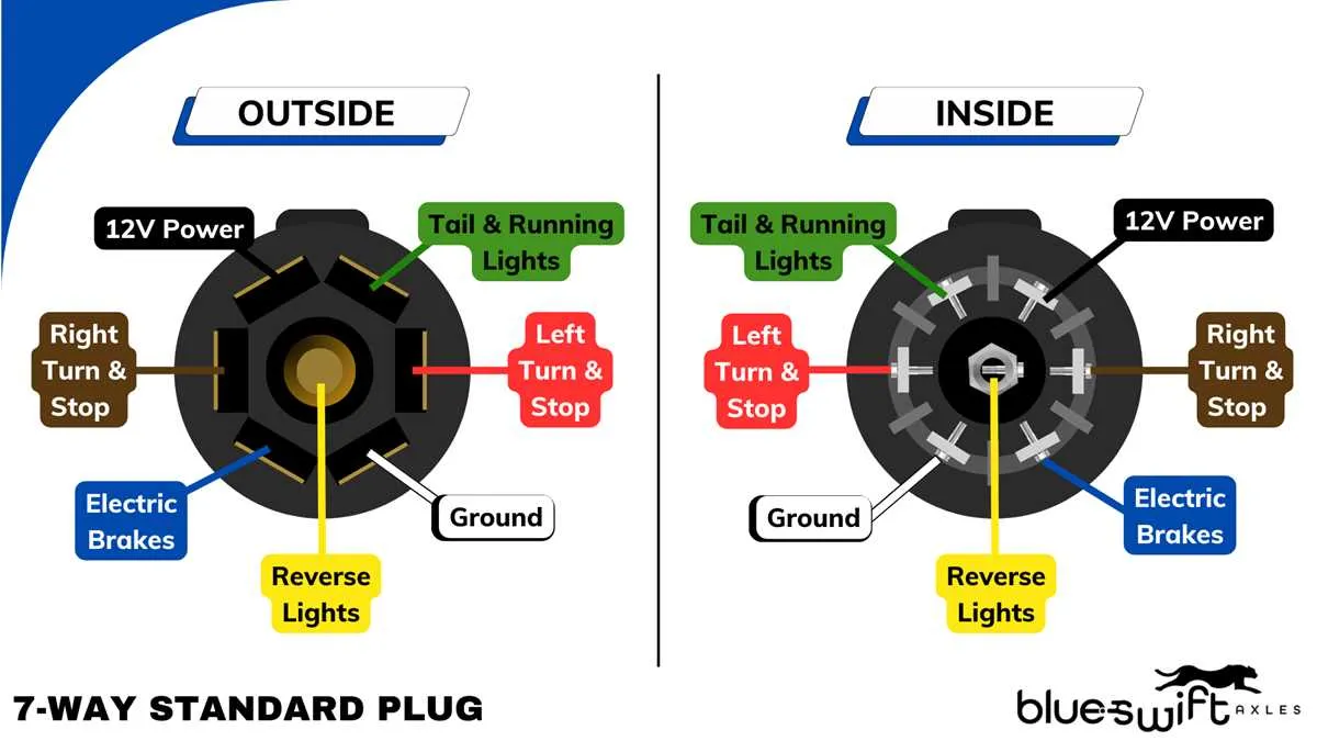
When setting up the electrical connections for your vehicle, it’s essential to know the roles of each wire in the 7-way connector. Here’s a breakdown of how each circuit should be wired and what functions they control:
- Ground: Typically the white wire, providing the necessary return path for the electrical current.
- Left turn signal: The yellow wire activates the left indicator lights on the connected unit.
- Right turn signal: The green wire powers the right turn signal for proper lighting functions.
- Running lights: The brown wire ensures that the exterior lights on the unit are illuminated when the vehicle’s lights are on.
- Reverse lights: The purple wire connects to the reverse lights on the towed unit, signaling when the vehicle is in reverse.
- Electric brakes: The blue wire delivers the signal to activate the braking system, ensuring proper deceleration coordination between the vehicle and towed unit.
- Auxiliary power: The black wire provides constant 12V power to charge the battery or power auxiliary accessories on the connected unit.
Accurate wiring is critical for the safe operation of the vehicle and the towed load. Each connection must be tested regularly to avoid potential issues. Make sure to use high-quality connectors and wire insulation to protect the system from wear and weather elements.
It’s important to verify that the vehicle’s 7-pin connector is compatible with the one on the towed unit. If there are any discrepancies in the wiring, consult the vehicle’s manual or an electrical professional to ensure the system operates smoothly and safely.
Step-by-Step Guide to Wiring Your Towing System
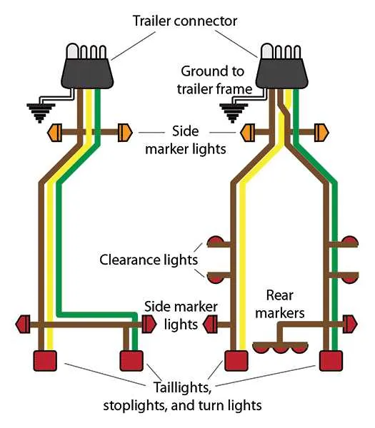
1. Gather Tools and Materials: Start by ensuring you have all necessary components for the installation, such as a 7-way connector, appropriate wire, connectors, fuses, and a multimeter for testing. You’ll also need a vehicle-specific harness and splicing tools to connect the wires correctly.
2. Identify Wires for Power Supply: Locate the power supply from the towing vehicle’s electrical system. Typically, this will come from the vehicle’s battery or alternator, ensuring it can handle the load required for the connection.
3. Grounding the System: Secure a solid ground connection to the towing vehicle’s chassis. This is crucial for the system to function correctly and safely. Use a bolt or screw that directly contacts the metal of the vehicle’s frame.
4. Connect the Signal Wires: The main connection includes wires for the left and right indicators, reverse lights, and the main power. For proper functionality, these wires must be routed to the correct locations on the connector, ensuring no shorts occur during operation.
5. Install the Protective Fuse: Insert a fuse on the power wire to protect against overload or short-circuiting. This will prevent potential damage to the electrical components in both the towing vehicle and the attached system.
6. Secure the Connector: Once all the wires are connected, carefully attach the 7-way connector to the designated area on the towing vehicle. Ensure it’s tightly secured and protected from environmental factors such as moisture and debris.
7. Testing and Verification: After all connections are in place, use a multimeter to test each wire for proper function. Make sure all signals, including the indicators and power source, work as expected. If something doesn’t function, check each wire for continuity and correct placement.
8. Final Check and Seal: Once tested, seal all connections with weatherproof tape or connectors to avoid corrosion. Inspect the entire setup, making sure wires are secured and away from any moving parts of the towing system.
Common Issues and Troubleshooting for 7 Pin Brake Wiring
Start by inspecting the connections for any loose or corroded terminals. Ensure that all contacts are clean and free of rust or dirt, as these can cause intermittent issues or complete failure in signal transmission.
If the brake light on the towing vehicle is functioning but not on the towed unit, check the grounding. A poor ground connection often results in a malfunction. Clean the grounding area and verify continuity to the frame of both units.
In cases where only one side of the lights operates, inspect the harness for possible short circuits or broken wires. A single broken wire can affect the entire circuit, so test each wire for continuity and repair as needed.
Fuses blow regularly? This could be due to a short in the wiring. Check the wires for chafing against metal surfaces or exposed spots that could lead to grounding issues. Replace any damaged sections of wire and ensure they are properly insulated.
If you notice that the signal works intermittently, it could indicate a problem with the relay. Test the relay functionality by swapping it with another working relay of the same type to rule out failure.
When the lights work, but the braking function is inconsistent or non-responsive, test the actuator connections and replace any faulty components. Additionally, ensure that the signal from the towing vehicle’s braking system is properly transmitted and received.
Always use a multimeter to check for voltage drop across the system. Significant voltage loss can indicate resistance in the wires, which may be due to damaged insulation, loose connectors, or underpowered electrical systems.