Ensure proper installation of the electrical system for the towed vehicle by following the outlined steps. Start by identifying the power source in the towing vehicle and connect it securely to the system in the trailer. Proper grounding is essential to avoid malfunctions, so be sure to use a reliable grounding point to complete the circuit.
Connect the power cables from the main control unit to the relevant components, including the lights and other signaling devices. Make sure to use the correct gauge wire, depending on the load and distance. Use heavy-duty connectors for better durability, especially if the vehicle will be exposed to harsh conditions.
Test the setup once all connections are made. Begin by checking the operation of the signal lights, brake lights, and turn indicators. If any issue arises, recheck each connection to identify any loose wires or improper grounding.
For brake control, ensure that the system is properly calibrated. This will help prevent excessive strain on either vehicle’s electrical system and ensure optimal performance under all conditions. Pay attention to the fuse ratings and replace them with the correct ones as needed.
Electrical Connection for Towed Vehicle’s Stopping System

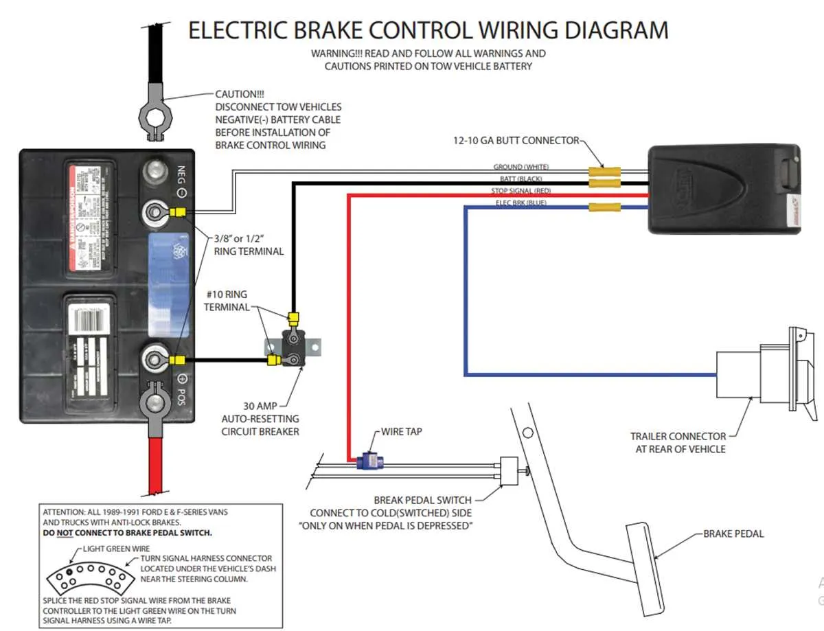
To ensure proper function of the stopping system in a towed vehicle, follow these essential connection steps:
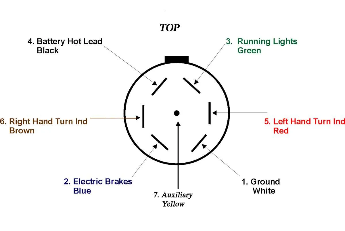
| Component | Wire Color | Function |
|---|---|---|
| Power Supply | Black | Provides main electrical feed from the tow vehicle |
| Signal Activation | Red | Activates the stopping mechanism when the towing vehicle’s brake is engaged |
| Ground | White | Completes the circuit by connecting to the tow vehicle’s chassis |
| Auxiliary Lights | Yellow | Controls turn signal and auxiliary lighting |
| Battery | Blue | Supports power backup for emergency stopping |
Ensure all connections are securely fastened and corrosion-resistant terminals are used for optimal safety and reliability.
Understanding the Basic Electrical Layout for Towed Vehicle Stopping Systems

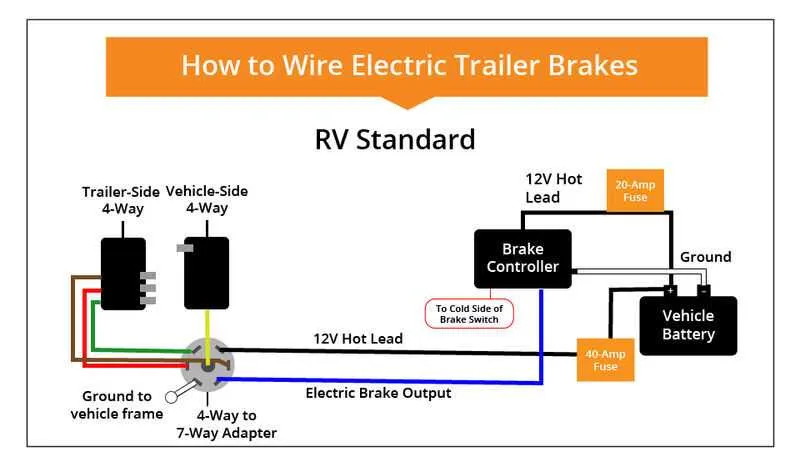
To ensure the proper function of stopping mechanisms, follow this guide for correct connection and distribution of power. The following steps outline the basic setup for safe operation:
- Start by connecting the power source from the towing vehicle to the control unit located on the towed unit. This serves as the central hub for energy distribution.
- Ensure the ground wire runs directly from the towed unit to the chassis of the towing vehicle, minimizing electrical resistance and ensuring safety.
- Use an appropriate fuse to protect the circuit from overcurrent, typically rated for the specific amperage needs of the system.
- Connect the signal wire to the control module, allowing it to relay the necessary commands to the system when activated by the towing vehicle’s braking force.
- Confirm that the auxiliary wire connects to a dedicated braking controller, which moderates the intensity of the stopping force based on conditions like speed or load weight.
Double-check all connections for corrosion and wear, as these can compromise efficiency and safety. Use high-quality connectors that are resistant to environmental factors.
How to Connect Electric Braking System to Your Vehicle’s Electrical Network

Start by ensuring your vehicle’s electrical system is ready to support the power requirements of the electric braking system. Use a 7-pin connector or a 6-pin plug for reliable power transfer. Make sure the voltage matches the system’s specifications to prevent damage.
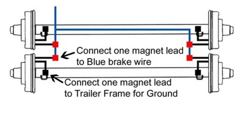
Next, locate the appropriate terminal on the connector that will handle the power supply for the braking unit. Typically, this is the blue wire, which should be connected to the system’s control unit for seamless activation.
To provide a secure connection, use crimp connectors or soldered joints to ensure low-resistance and minimize the risk of power loss. Insulate the exposed wires with heat shrink tubing or electrical tape to prevent wear and corrosion over time.
Ensure the ground connection is firmly attached to the chassis of the towing vehicle. A poor ground connection can lead to erratic performance, causing the system to malfunction.
Finally, verify the system’s performance before fully relying on it. Perform a system test by slowly activating the electrical unit, checking for even braking force and a quick response time. Make any adjustments as necessary to achieve optimal performance.
Common Electrical Problems and Solutions for Towing Vehicle Connections
Faulty Ground Connections are a frequent issue that can cause unreliable performance. Ensure that the grounding is solid by cleaning contact points and using corrosion-resistant connectors. A poor ground can lead to inconsistent signals or failure to activate the stopping mechanism.
Loose or Corroded Pins can disrupt proper contact between connectors. Inspect the pins regularly for wear, dirt, or corrosion. Use dielectric grease to prevent moisture buildup and ensure a secure connection. If pins appear damaged, replace the entire connector assembly.
Blown Fuses often occur due to overloading or short circuits. Check the fuse box and replace any blown fuses with the correct amperage. Always carry spares of various ratings to handle different electrical needs.
Worn Wiring Insulation can lead to exposed wires, which may cause short circuits or electrical fires. Inspect the insulation regularly for cracks, abrasions, or wear. If damaged, replace the wire sections immediately to avoid dangerous situations.
Inconsistent Voltage can result from an insufficient power supply or issues within the towing vehicle. Check the voltage output from the towing vehicle’s electrical system. If it drops below required levels, troubleshoot the vehicle’s electrical components or alternator.
Incorrect Connector Orientation can result in malfunctioning components. Verify that all connections are made correctly, as incorrect orientation may cause reverse polarity issues or prevent proper activation of connected parts.