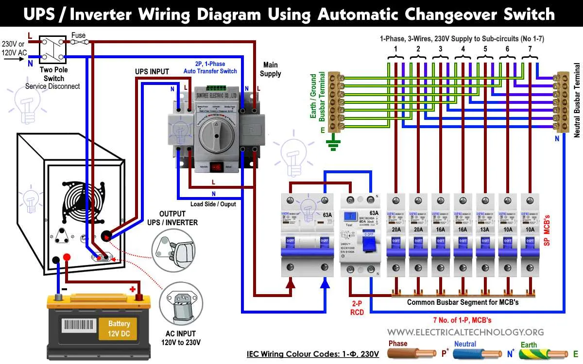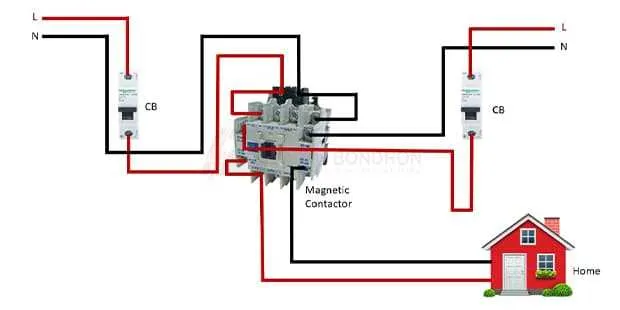
To ensure a smooth transition between power sources, proper connection of electrical components is essential. Begin by identifying the key terminals and their roles in the system. The main input terminal should be securely attached to the power supply, while the secondary input connects to your backup generator. This ensures that when the primary source fails, the secondary will automatically kick in without interruption.
Pay close attention to the configuration of the ground and neutral terminals. The ground terminal must always be connected to the earth ground to avoid potential hazards. The neutral terminal needs to be properly bonded to the system, especially when working with a generator to prevent any electrical imbalances.
Check the voltage specifications for each component before installation. Using incompatible voltage levels can cause significant damage or even render the system inoperable. Always confirm that your system components match the specifications of both the main supply and backup generator.
Ensure that each terminal is tightly secured, and there is no risk of loose connections. Poor connections can lead to overheating or voltage fluctuations that might disrupt your electrical supply. Use the appropriate connectors and tools to achieve a solid, safe connection.
Lastly, after installation, test the system under load conditions. Verify that the secondary power source kicks in seamlessly when the primary fails, and ensure there is no delay in supplying power. Proper testing is crucial for avoiding failures during critical times.
Installation Guidelines for Power Control Systems
To ensure a reliable and safe connection between your generator and home grid, follow these steps:
- Ensure that the power source and load are disconnected before starting the setup.
- Identify the input and output terminals of the power control system, making sure you match them correctly with the source and load circuits.
- Use appropriately rated cables that can handle the expected current and voltage levels.
- Connect the neutral wire from the generator to the designated terminal on the system. Be cautious to avoid mixing it with ground connections.
- Wire the generator’s output terminals to the system’s input side, ensuring a solid and secure connection for optimal conductivity.
Always verify the integrity of the ground connections. A proper grounding system is crucial for safe operation and protection from electrical faults.
Once the connections are made, test the system by powering up the generator and verifying that the load receives power correctly. Check the voltage levels and ensure they match the specified values for your system.
- Regularly inspect all connections for signs of wear or corrosion.
- Perform periodic maintenance to ensure the system operates at maximum efficiency and safety.
How to Read a Power Control System Layout

Start by identifying the power sources. Typically, you will have two distinct inputs: one from the grid and one from the backup generator. Look for lines that show where each source connects to the load center, ensuring you understand how the two systems are isolated from one another when not in use.
Next, locate the components responsible for the automatic selection of the power source. These are often represented by symbols such as a two-position contact or relay, which engage when the primary source fails. Check the position of each relay and whether it’s normally open or closed under default conditions.
Focus on the load circuits next. These are the lines connecting your essential devices to the power system. You’ll see these paths split or merge, indicating the flow of electricity under different scenarios. Pay attention to the protection mechanisms like fuses or breakers that prevent overloads in any particular section.
Understand the auxiliary connections. These include connections for monitoring and control functions. They may involve communication lines between the unit and the generator or control panel. Ensure you note which ones are for emergency signaling or for status indicators.
Finally, verify the grounding paths. It’s crucial to check how the system is grounded to avoid any electrical hazards. The grounding is often indicated with a special symbol or a thicker line running throughout the setup.
Common Wiring Errors in Backup Power Installation
Ensure all connections are properly grounded to avoid electrical faults. A poor or missing ground connection can result in overheating or system failure. Double-check the grounding terminals, ensuring that the connection to the main panel is secure and meets the code requirements.
Never confuse the line and load terminals. Miswiring these two can lead to a complete malfunction. Verify that the input power and the output power are connected to their designated terminals to ensure the correct direction of electricity flow.
Avoid using wires that are not rated for the current they will carry. Underestimated wire gauge sizes can cause overheating and even fires. Always adhere to the manufacturer’s recommendations for wire gauge to handle the expected load safely.
Incorrectly connecting the neutral wire is a common mistake. The neutral should not be connected to the wrong terminal or shared across multiple circuits unless specifically designed to do so. Check that the neutral is isolated properly in the system to prevent unwanted feedback or electrical shock hazards.
Improperly configured bypass connections can result in parallel power sources feeding into each other, risking damage to the equipment. Ensure the configuration clearly defines the cutoff points, preventing cross-feeding between the grid and the backup source.
Incorrect polarity is another frequent issue. Reversing the hot and neutral wires can cause damage to both the power source and your appliances. Always test polarity before completing the installation to avoid short circuits or damaging sensitive electronics.
Ensure that the transfer mechanism operates as intended. If the control panel is not wired correctly, it may fail to detect when power loss occurs or improperly activate backup power. Test the system under different conditions to confirm that the automatic transfer sequence functions correctly.
Lastly, check for loose or improperly tightened terminal connections. Loose connections can create arcing, leading to system failure or even fires. Tighten all terminals properly and use a torque wrench to meet the required specifications.
Step-by-Step Guide to Connecting a Backup Power System
1. Begin by turning off the main power supply to the electrical panel to ensure safety during installation.
2. Mount the device securely near the electrical panel. Ensure that it is within reach of the circuit breakers, but far enough to avoid interference with regular operation.
3. Connect the main power line from the utility to the designated input terminal of the backup device. This is usually marked as the “main” or “utility” connection.
4. Run separate cables from the output terminals of the device to the essential circuits that need backup power. Use the proper gauge wire based on the amperage requirements of each circuit.
5. Install a dedicated circuit breaker for each of the backup circuits, ensuring they are rated correctly to handle the electrical load. Attach these breakers to the designated spots in the panel.
6. Connect the ground wire from the backup unit to the grounding bus bar in the electrical panel. Ensure all metal parts of the system are properly grounded to prevent electrical hazards.
7. Double-check all connections for tightness and proper insulation. Avoid any exposed wire ends that could lead to shorts or electrical shocks.
8. Power up the system by turning on the backup unit and then gradually restoring power to the essential circuits. Test the setup by simulating a power outage and verifying that backup power flows to the designated circuits.
9. Document the installation by labeling the circuits powered by the backup system for future reference and troubleshooting.
10. Always consult a licensed electrician if you’re unsure about any part of the installation process.