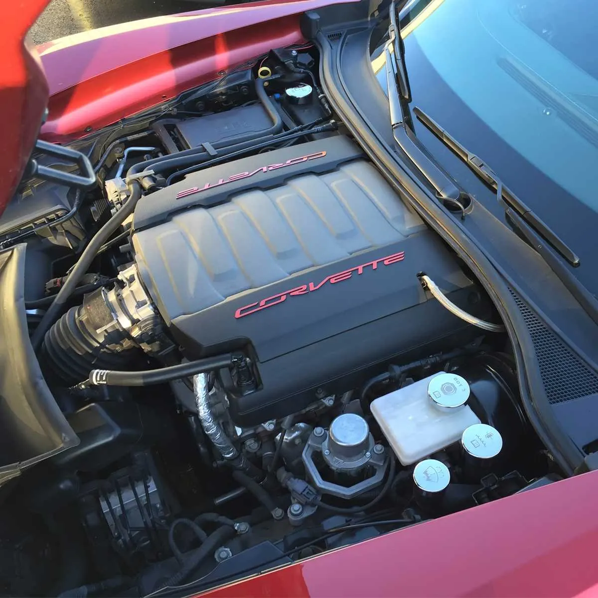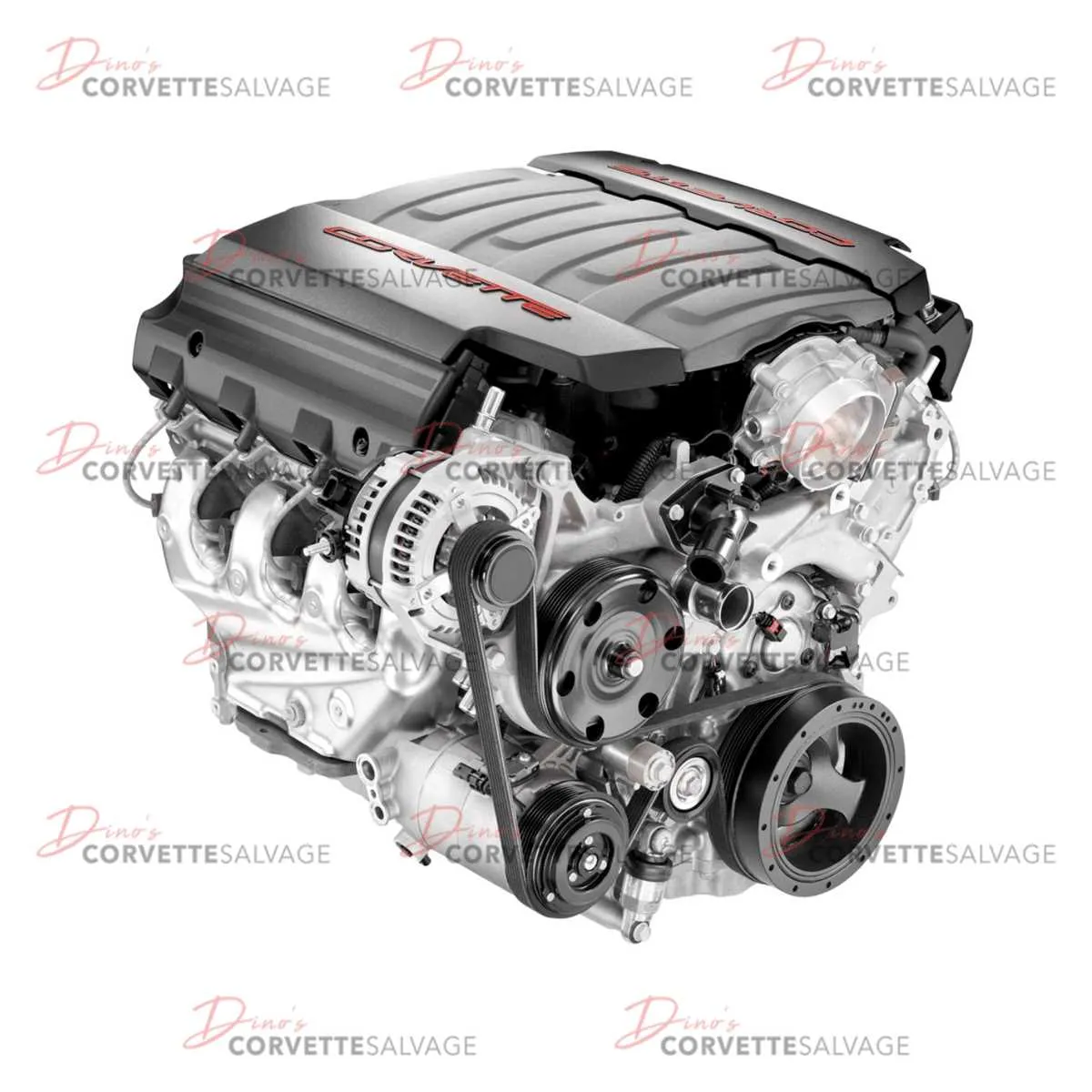
To understand the layout of the powerplant and associated components, consult the specific schematics for the vehicle’s front section. These visuals are indispensable for anyone working on the repair, upgrade, or troubleshooting of the car’s performance systems. They provide clear, precise illustrations that indicate the exact positioning of each element, making maintenance procedures more efficient and less prone to error.
For optimal results, always refer to high-resolution, factory-sourced sketches when performing diagnostics or modifications. These resources highlight key areas such as the intake manifold, cooling system connections, and exhaust routing. Proper knowledge of the layout will significantly ease the process of identifying issues or replacing parts in the high-performance sections.
Ensure correct identification of critical systems like the fuel delivery network and turbocharging elements, as mishandling can lead to severe performance drops. Pay close attention to the placement of sensors and electrical connections, as these components directly affect the vehicle’s overall functionality.
For those who regularly work on similar high-powered vehicles, having a thorough understanding of the internal structure is essential. Always double-check with detailed schematics before beginning any work, as this can save valuable time and avoid costly mistakes.
Engine Bay Layout for Corvette ZR1
To effectively understand the layout of the performance parts in the Corvette’s engine bay, follow these key steps for clarity and precision:
- Positioning of the Supercharger: The supercharger is centrally placed, providing optimal airflow to the intake system. Make sure it is aligned properly to ensure maximum boost efficiency.
- Cooling System Components: The radiator sits at the front with the heat exchanger system closely integrated with the air-to-water intercooler. Check for proper coolant levels and secure fittings to avoid leaks.
- Electrical Wiring and Sensors: Wiring harnesses are routed along the sides to prevent interference with high-temperature areas. Ensure that all connectors are firmly secured to avoid power loss or sensor malfunctions.
- Air Intake Path: The intake ducts are designed to reduce airflow restriction. Regular inspection of these components ensures the engine receives a constant supply of fresh air without obstructions.
- Exhaust System Layout: The exhaust manifolds are positioned near the front of the engine to optimize the flow of exhaust gases. Keep these areas free of debris and inspect for any signs of wear or leaks.
Regular maintenance and inspection of these areas will ensure the high-performance capabilities of your vehicle remain intact. Focus on securing any loose parts and replacing damaged components promptly to prevent performance drops or system failures.
Identifying Key Components in the 2019 ZR1 Engine Bay

Start by locating the supercharger on the top left of the bay. This powerful component is integral for forced air induction and sits just above the intake manifold. Adjacent to it, the fuel rails run along the engine block, distributing fuel evenly to each injector. Pay close attention to the coolant reservoir, which sits near the front, close to the radiator, ensuring optimal temperature regulation.
On the driver’s side, you’ll find the alternator, positioned next to the serpentine belt, which plays a critical role in power generation for electrical systems. To the right of it, the air intake system directs airflow through the front of the car into the combustion chambers, providing the engine with necessary oxygen for performance.
For electrical components, focus on the fuse box located near the firewall. This is crucial for circuit protection and ensures the vehicle’s electrical systems function properly. Behind the fuse box, the battery is securely mounted, providing the power needed for the vehicle’s starting system and other critical electrical functions.
The timing cover, often overlooked, protects the internal mechanisms, including the camshaft and crankshaft gears. It’s essential for maintaining the synchronization of the engine’s moving parts. Also, ensure to inspect the belt tensioner and pulleys, as these regulate the operation of belts connecting key components like the power steering pump and air conditioning compressor.
Understanding the Layout of Cooling and Airflow Systems
Ensure the air intake system remains clean and unobstructed for optimal airflow. Properly functioning air intakes direct cool, dense air to the intake manifold, increasing engine efficiency. Blockages in these pathways can lead to overheating and reduced performance.
Position the radiator fan close to the heat source to maximize cooling efficiency. The fan should operate at variable speeds, driven by temperature sensors, to respond dynamically to changes in heat levels. Insufficient airflow can result in excessive heat buildup, compromising engine performance.
Routing of the cooling hoses should minimize sharp bends to prevent restrictions in coolant flow. Any kinks or damaged sections must be replaced immediately to avoid loss of cooling capacity. Use high-quality hoses to resist degradation from extreme temperatures and pressure.
Direct airflow across critical components, such as the intercooler and oil coolers, to ensure they remain within the recommended temperature range. Pay attention to the placement of cooling ducts, which should guide air through the system efficiently without creating turbulence or backpressure.
Regularly inspect the heat shields and insulation materials surrounding high-temperature areas. These components prevent heat from radiating to sensitive parts, improving both longevity and performance. Any gaps or signs of wear should be addressed promptly.
Ensure that the airflow routing around the exhaust system is unobstructed. Hot air generated by the exhaust must be vented quickly to prevent heat soak, which can affect the performance of the turbochargers and other temperature-sensitive components.
Wiring and Electrical System Placement in the 2019 ZR1 Bay

Ensure that all wiring is routed along the designated harness channels to prevent potential damage from heat or mechanical interference. The primary power distribution block is located near the left front corner, with the fuse box positioned to the right for easy access. For optimal function, ensure that ground connections are tight and free of corrosion, particularly around the battery terminals and chassis contact points.
Electrical components, such as the alternator and the main wiring junction, should be securely mounted to avoid excessive vibration, which can lead to wear over time. Pay special attention to the positioning of the throttle body and air intake sensor wiring to ensure they do not interfere with moving parts or hot surfaces. Use protective sleeving where necessary, especially in areas with high temperatures like near the exhaust manifold or turbocharger lines.
The harness near the intake manifold should be routed away from direct airflow to minimize the risk of short circuits caused by moisture or debris. Additionally, check that the wiring to the ignition coils and sensors is not pinched or under strain, as improper placement can cause erratic performance. For better longevity, use zip ties and clips designed to hold wires firmly in place while allowing enough slack for thermal expansion.
Review the placement of the main ECU connection and ensure it’s properly shielded from moisture or contamination. The connector must not show signs of wear and should be tested regularly for continuity. When inspecting, confirm that each wire is clearly labeled and that no wires are exposed to the elements, which could compromise the system’s integrity.