If you are a proud owner of a vehicle equipped with Uconnect, having a wiring diagram handy is essential. Uconnect is a cutting-edge system that connects your vehicle to the digital world, offering features like hands-free calling, smartphone integration, navigation, and entertainment options. Understanding the wiring behind this advanced technology can be helpful in troubleshooting issues, making upgrades, or simply gaining a better understanding of how your Uconnect system functions.
This comprehensive guide will walk you through the basics of Uconnect wiring diagrams, providing a clear and detailed explanation of the various components and connections involved. Whether you are a DIY enthusiast looking to customize your Uconnect system or a technician searching for a reliable reference, this article will serve as a valuable resource.
We will cover the fundamental elements of a Uconnect wiring diagram, including the main unit, wiring harnesses, speakers, microphone, display screen, and any optional accessories. Additionally, we will delve into how different wires and connectors interact, enabling the seamless integration of Uconnect with your vehicle’s electrical and audio systems.
By the end of this guide, you will have a solid grasp of Uconnect wiring diagrams, equipping you with the knowledge needed to tackle any wiring-related projects or troubleshoot issues that may arise with your Uconnect system. So, let’s dive in and unlock the potential of your Uconnect-equipped vehicle!
What is Uconnect?
The Uconnect system is an in-vehicle connectivity platform developed by Fiat Chrysler Automobiles. It is designed to provide drivers and passengers with a wide range of features and services that enhance the overall driving experience.
One of the key functionalities of Uconnect is its integration with smartphones. By connecting a compatible smartphone to the Uconnect system via Bluetooth or USB, drivers can access a variety of smartphone apps and features directly from the vehicle’s touchscreen display. This allows for hands-free calling, messaging, navigation, and music streaming.
In addition to smartphone integration, Uconnect also offers other features such as voice commands, vehicle diagnostics, entertainment options, and safety services. For example, drivers can use voice commands to make phone calls, send text messages, or control the vehicle’s audio system without taking their hands off the wheel. Uconnect also provides access to real-time vehicle information, such as fuel levels, tire pressure, and maintenance alerts.
Overall, Uconnect is a comprehensive connectivity platform that brings together various technologies and services to provide a seamless and convenient driving experience. Whether it’s staying connected to your smartphone, accessing entertainment options, or staying informed about your vehicle’s health, Uconnect aims to make driving safer, more enjoyable, and more connected.
Importance of having a wiring diagram
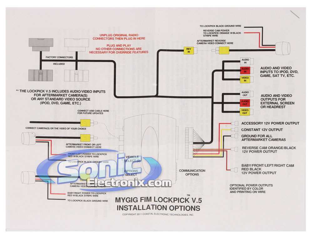
Having a wiring diagram is essential when it comes to troubleshooting and repairing electrical systems, including the Uconnect system in vehicles. A wiring diagram is a visual representation of the electrical connections and components in a system. It shows the pathways and connections between different components, such as the Uconnect module, radio, speakers, and other relevant parts.
One of the primary benefits of having a wiring diagram is that it allows technicians to identify and understand the overall layout of the electrical system. By referencing the diagram, they can easily locate specific wires, connectors, and components, helping them navigate through the complex network of electrical connections. This simplifies the troubleshooting process and saves valuable time.
The wiring diagram also provides crucial information about the electrical functions and interactions between different components. It helps technicians understand how signals and power flow through the system, aiding in diagnosing issues and identifying potential problem areas. Without a wiring diagram, technicians would have to rely on guesswork and trial-and-error, which can be time-consuming and less effective.
Furthermore, a wiring diagram is necessary when making modifications or adding aftermarket components to the Uconnect system. It serves as a guide for properly integrating new devices into the existing electrical system without causing any conflicts or issues. Without a wiring diagram, it would be challenging to ensure the correct connections and prevent damage to the system.
In summary, having a wiring diagram is crucial for accurate troubleshooting, repair, and modification of the Uconnect system. It provides technicians with a visual representation of the electrical connections and components, aiding in locating specific wires, understanding electrical functions, and ensuring proper integration of new components. With a wiring diagram, technicians can work more efficiently and effectively, resulting in a faster and more reliable diagnosis and repair process.
Main components of Uconnect
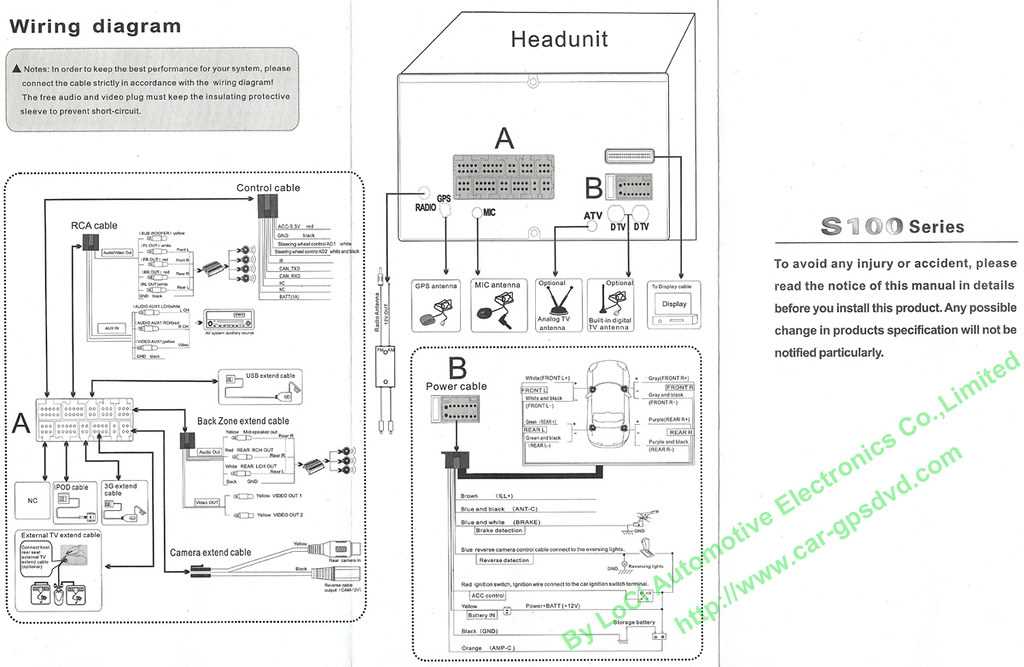
The Uconnect system is a comprehensive in-vehicle infotainment system designed to enhance the driving experience. Its main components include:
1. Display Screen
The display screen is the central interface of the Uconnect system. It provides access to various features and functions, including audio controls, navigation, climate control settings, and phone connectivity. The screen size and resolution may vary depending on the vehicle model and trim level.
2. Control Panel
The control panel consists of physical buttons and knobs that allow the driver and passengers to interact with the Uconnect system. These controls are typically located on the center console or steering wheel and provide quick and easy access to key functions, such as volume control, menu navigation, and voice commands.
3. Audio System
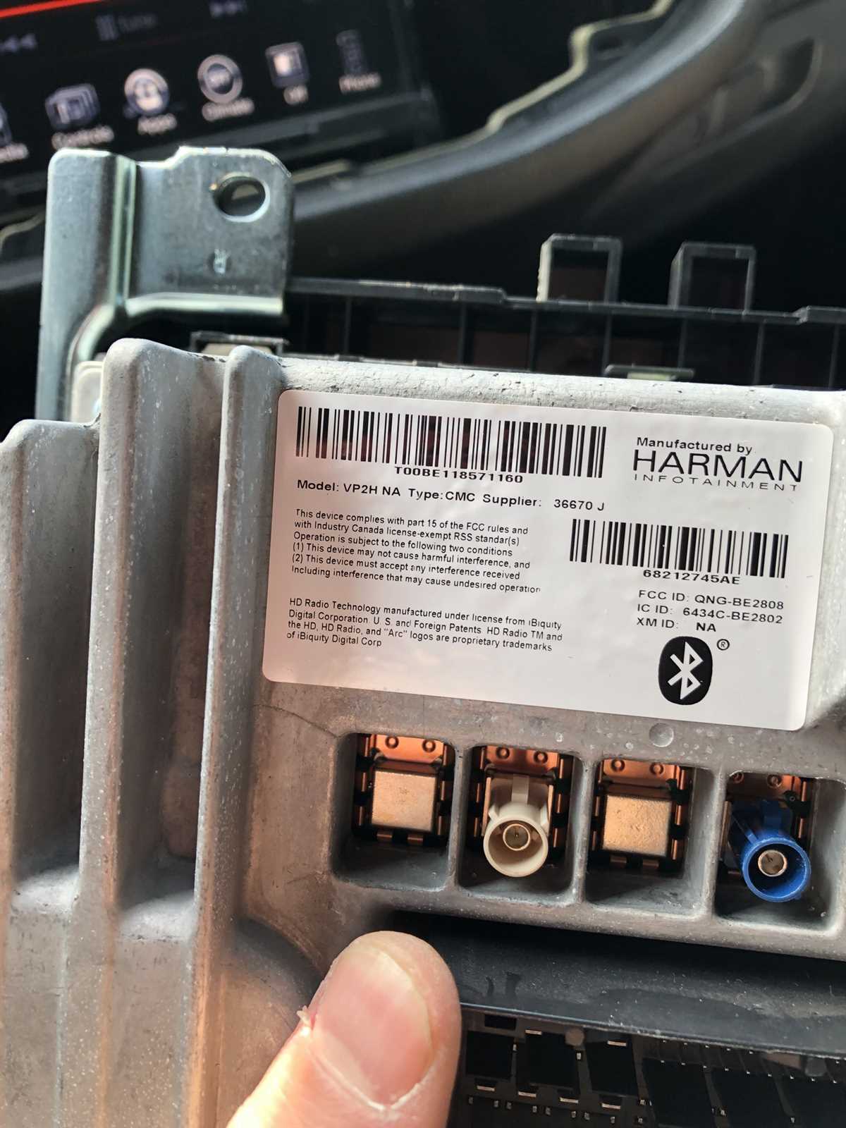
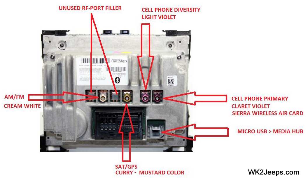
The Uconnect system is integrated with the vehicle’s audio system, allowing users to listen to music, radio, podcasts, and other audio content. It supports various sources, including AM/FM radio, satellite radio, Bluetooth streaming, USB connectivity, and auxiliary inputs. Some vehicles may also come equipped with premium audio systems for enhanced sound quality.
4. Navigation System
The Uconnect system often includes a built-in navigation system, providing turn-by-turn directions and real-time traffic updates. The navigation system utilizes GPS technology to determine the vehicle’s location and provides visual and audible guidance for reaching a destination. Users can input addresses, search for points of interest, and customize route preferences.
5. Connectivity Options
Uconnect offers various connectivity options to keep drivers and passengers connected on the go. This includes Bluetooth hands-free calling, which allows users to make and receive calls through the vehicle’s audio system. It also supports smartphone integration, enabling users to access their phone’s apps, messages, and other features directly on the Uconnect screen. Additionally, some Uconnect systems offer Wi-Fi hotspot capabilities for internet connectivity.
In summary, the main components of Uconnect include the display screen, control panel, audio system, navigation system, and connectivity options. These components work together to provide a seamless and intuitive infotainment experience for drivers and passengers in modern vehicles.
How the wiring diagram is organized
When it comes to understanding the wiring diagram of a Uconnect system, it is important to note how the information is organized. The diagram typically consists of various symbols and lines that represent the connections between different components of the system. These symbols and lines are arranged in a logical manner to facilitate understanding and troubleshooting.
The wiring diagram is often divided into sections or diagrams that focus on specific aspects of the system. For example, there may be separate diagrams for the power supply, audio inputs and outputs, and control signals. This division allows for a more detailed and comprehensive understanding of the system as a whole.
Within each section or diagram, the components and their connections are clearly labeled and represented by specific symbols. These symbols, which may include lines, dots, or other shapes, indicate how the components are connected and how the electrical signals flow through the system.
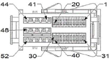
Additionally, the wiring diagram may also include important information such as wire colors, wire gauges, and pin numbers. This information is crucial for proper installation, repair, and maintenance of the Uconnect system.
Overall, the organization of the wiring diagram plays a critical role in simplifying the understanding and troubleshooting of the Uconnect system. By providing clear and detailed representations of the system’s components and connections, the diagram enables technicians and users to identify and resolve any issues that may arise.
Reading the diagram symbols
When working with a Uconnect wiring diagram, it is important to understand how to interpret the various symbols and abbreviations used. These symbols provide valuable information about the different components, connections, and electrical circuits in the diagram.
Wire symbols: Wires are represented by lines in the diagram. Different line styles and colors are used to indicate the type of wire and its function. For example, a solid black line is often used to represent a ground wire, while a dashed line may indicate a wire with a different voltage or current level.
Component symbols: Components such as switches, sensors, relays, and connectors are represented by specific symbols in the diagram. These symbols vary depending on the component type but typically have a unique shape or design that makes them easily recognizable. For example, a switch may be represented by a circle with a line through it, while a relay may be depicted as a rectangular box with several input and output terminals.
Abbreviations: Wiring diagrams often include abbreviations to save space and simplify the diagram. These abbreviations represent various electrical terms and functions. For example, “P” may stand for power, “GND” for ground, and “IGN” for ignition. It is important to refer to the diagram’s legend or key to understand the meaning of these abbreviations.
Arrows: Arrows in a wiring diagram indicate the direction of current flow. These arrows are typically drawn on wires or between components to show the path of electrical current. Understanding the direction of current flow is crucial for correctly interpreting the diagram and troubleshooting electrical issues.
Color coding: In some wiring diagrams, colors may be used to denote the different wires or connections. For example, a red wire may indicate power supply, while a blue wire may represent a ground connection. It is important to refer to the diagram’s color code key to understand the meaning of these colors.
Overall, understanding the symbols and abbreviations used in a Uconnect wiring diagram is essential for effectively troubleshooting and repairing the electrical system. Taking the time to familiarize yourself with these symbols will greatly enhance your ability to read and interpret the diagram accurately.
Identifying the different wires
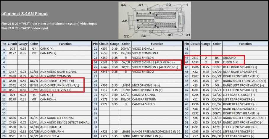
When working with a Uconnect wiring diagram, it is important to be able to identify the different wires and understand their roles in the system. Each wire serves a specific purpose and knowing which wire is responsible for what function can help troubleshoot any issues or make any necessary connections.
Power wires: The power wires are responsible for supplying electricity to the Uconnect system. These wires usually have a red or orange color and are connected to the battery or the vehicle’s electrical system.
Ground wires: Ground wires are necessary for completing the electrical circuit and ensure that there is a solid connection to the vehicle’s chassis. These wires often have a black color and are connected to a metal part of the vehicle.
Speaker wires: Speaker wires are used to connect the Uconnect system to the speakers in the vehicle. These wires will vary in color depending on the specific speaker location and type of connection (positive or negative).
Control wires: Control wires are responsible for communication between various components of the Uconnect system. These wires can include the CAN bus wire, which allows for data exchange between different modules, or other communication wires specific to certain features of the system.
Accessory wires: Accessory wires are used to connect additional features and accessories to the Uconnect system. These wires may include connections for external audio devices, antennas, or other optional features.
Input/output wires: Input and output wires allow for the exchange of data between the Uconnect system and external devices. These wires can include connections for USB ports, audio/video inputs, or external controls such as steering wheel controls.
Understanding the different wires in a Uconnect wiring diagram is crucial for proper installation, troubleshooting, and customization of the system. It is important to refer to the specific diagram for your vehicle model to ensure accurate identification of the wires.
Common issues and troubleshooting with Uconnect wiring
The Uconnect system is a popular feature found in many vehicles, offering a range of connectivity and entertainment options. However, like any electrical system, issues can arise with the wiring that connects the Uconnect system to the vehicle’s components. Here are some common issues and troubleshooting tips for Uconnect wiring:
1. Connection problems:
One of the most common issues with Uconnect wiring is poor or loose connections. This can result in intermittent connectivity, loss of power to certain components, or complete system failure. To troubleshoot this issue, it is important to visually inspect all wiring connections associated with the Uconnect system. Look for any loose or disconnected wires, and make sure all connectors are securely plugged in. If any issues are found, they should be repaired or replaced as necessary.
Insurance companies and motoring organisations have warned of a new technique being used by thieves to steal cars.
2. Wiring damage:
Another common issue with Uconnect wiring is physical damage. This can occur due to accidents, poor installation, or general wear and tear. Damaged wiring can cause a variety of issues, including loss of power, short circuits, or interference with other components. To troubleshoot this issue, carefully inspect the Uconnect wiring for any signs of damage, such as frayed or exposed wires. If any damage is found, it should be repaired or replaced promptly to prevent further issues.
3. Compatibility problems:
Sometimes, Uconnect wiring issues can arise due to compatibility problems between the Uconnect system and the vehicle’s components. This can result in features not working properly or not working at all. To troubleshoot this issue, it is important to ensure that the Uconnect system is compatible with the vehicle’s components. Check the manufacturer’s specifications and guidelines to ensure compatibility. If there are any compatibility issues, consider consulting a professional for assistance or upgrading the system if necessary.
Overall, troubleshooting Uconnect wiring issues requires careful inspection, attention to detail, and potentially professional assistance. By identifying and addressing these common issues, the connectivity and functionality of the Uconnect system can be maintained and enjoyed to its fullest extent.
Identifying wiring problems
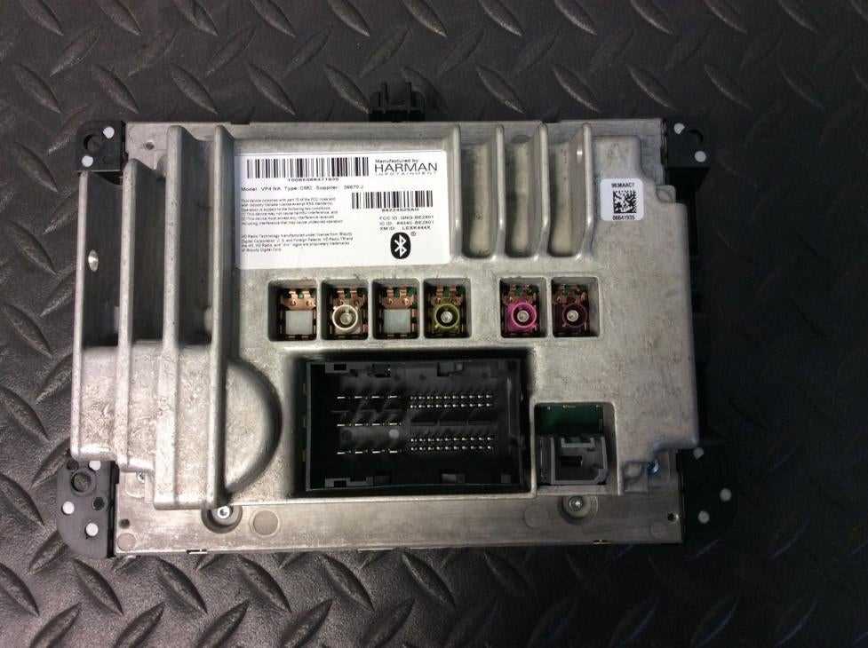
Wiring problems can be frustrating and time-consuming to diagnose and fix. However, with the right tools and knowledge, you can identify and resolve them efficiently. Here are some steps to help you identify wiring problems:
- Visual inspection: Start by visually inspecting the wires, connectors, and plugs for any signs of damage, such as frayed or exposed wires, loose connections, or burnt marks. This will give you an initial indication of potential issues.
- Testing continuity: Use a multimeter to test the continuity of the wires. This will help you determine if there are any breaks or shorts in the wiring. Check for continuity between the appropriate connection points to ensure proper connectivity.
- Circuit analysis: If you suspect a specific circuit to be the source of the problem, perform a circuit analysis. This involves tracing the wires and checking for any abnormalities, such as incorrect connections or faulty components.
- Signal testing: If the issue is related to a specific signal or voltage, use a signal tester to check for proper signal strength and consistency. This will help you pinpoint the exact location of the problem within the wiring system.
- Consulting wiring diagrams: Refer to the Uconnect wiring diagram or any other relevant diagrams to understand the wiring connections and components involved in the system. This will assist you in identifying any discrepancies or errors in the wiring setup.
- Seeking professional help: If you are unable to identify or fix the wiring problem on your own, it is advisable to seek professional help. Experienced technicians can diagnose and repair complex wiring issues effectively.
Remember, identifying wiring problems requires patience, attention to detail, and a systematic approach. By following these steps, you can troubleshoot and resolve wiring issues in your Uconnect system or any other wiring system effectively.
Q&A:
How can I identify a wiring problem?
To identify a wiring problem, you can start by checking for any visible damage or wear on the wiring itself. You can also use a multimeter to check for continuity and proper voltage levels. Additionally, inspecting the connections and terminals for loose or corroded wires can help identify issues.
What are some common signs of a wiring problem?
Common signs of a wiring problem include flickering lights, frequent tripping of circuit breakers, overheating outlets or switches, and the presence of burning or strange smells near electrical outlets. Other signs may include appliances or devices not working properly or consistently.
Can a wiring problem be dangerous?
Yes, a wiring problem can be dangerous as it can lead to electrical fires, electrocution, or damage to electrical appliances or devices. It is important to address any wiring problems promptly and have them resolved by a qualified electrician.
How can I fix a wiring problem myself?
Fixing a wiring problem yourself can be dangerous if you do not have the necessary knowledge and skills. It is generally recommended to hire a qualified electrician to diagnose and fix any wiring issues. They will have the expertise and tools required to safely address the problem.
How much does it cost to fix a wiring problem?
The cost to fix a wiring problem can vary depending on the extent of the issue, the location, and the complexity of the wiring system. It is best to contact a few electricians for a quote to get an accurate estimate for the specific problem you are facing.
What are common signs of wiring problems in a house?
Common signs of wiring problems in a house include flickering lights, frequent breaker trips, outlets or switches that are warm to the touch, burning smells, and discolored or charred outlets or switches.
How can I identify a wiring problem in my home?
You can identify a wiring problem in your home by checking for signs such as flickering or dimming lights, outlets or switches that are not working, a burning smell, tripping breakers, buzzing or sizzling sounds, and discolored or charred outlets or switches. In some cases, you may also find frayed or damaged wires.