
The uses relationship is an important element in a use case diagram, which is a graphical representation of the interactions between actors and use cases in a system. It depicts how an actor interacts with a use case to achieve a specific goal or task. The uses relationship helps to identify the different flows of actions and functionalities that an actor can initiate, as well as the dependencies between use cases.
In a use case diagram, the uses relationship is represented by an arrow pointing from the actor to the use case. This arrow represents the flow of actions from the actor to the use case, indicating that the actor uses the functionality provided by the use case to achieve their goal. The uses relationship is a unidirectional relationship, meaning that the actor can initiate the use case, but the use case does not initiate the actor.
The uses relationship is particularly useful in identifying the different ways in which an actor can interact with a use case. It helps to outline the various paths or scenarios that the actor can take to achieve their goal or complete their task. By understanding the uses relationship, stakeholders can better understand the functionality provided by the system and how it aligns with the needs and requirements of the actors.
Overall, the uses relationship in a use case diagram is a crucial element in understanding the interactions between actors and use cases in a system. By visualizing this relationship, stakeholders can gain insights into the different flows of actions and functionalities that actors can initiate, and how they contribute to the overall functioning of the system.
What is a use case diagram?
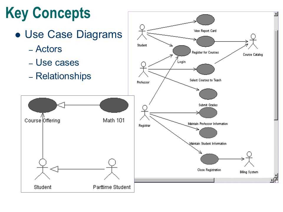
A use case diagram is a type of behavioral diagram in the Unified Modeling Language (UML) that represents the interactions between an external actor (user, system, or another entity) and a system to achieve a specific goal. It provides a visual representation of the functional requirements of a system and how those requirements are affected by different actors.
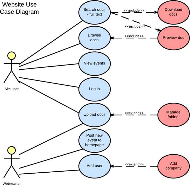
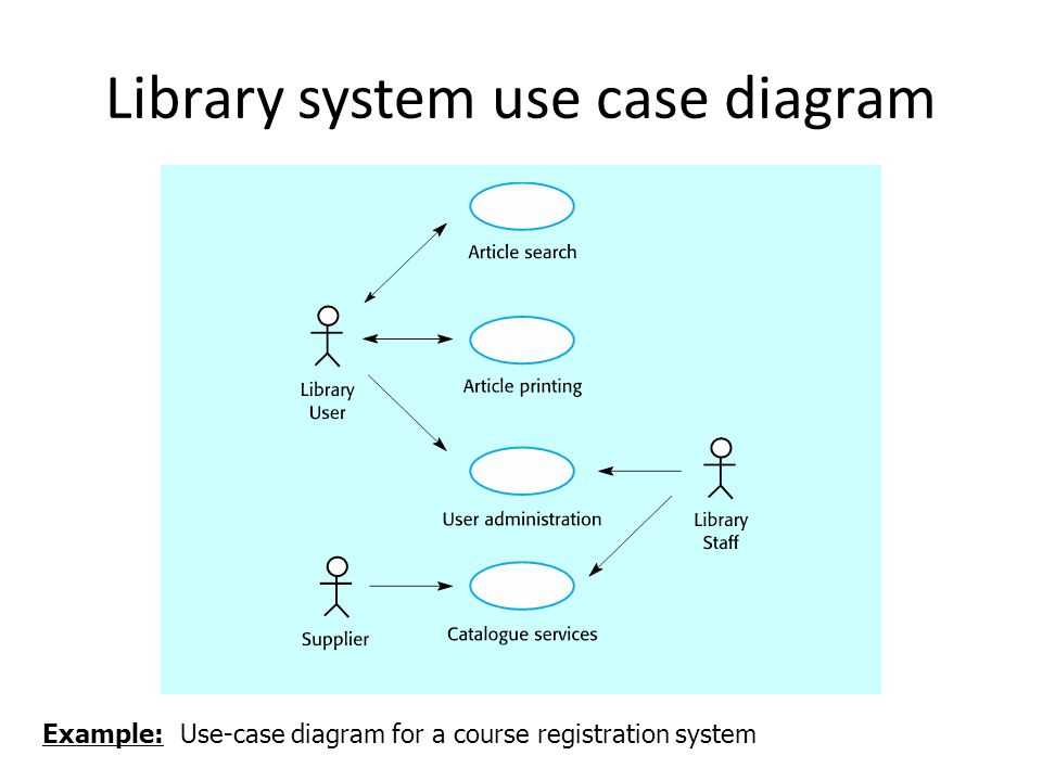
In a use case diagram, use cases are depicted as ovals or ellipses, which represent a specific functionality or behavior that the system must perform. Actors, on the other hand, are represented by stick figures or other shapes to represent the different entities that interact with the system.
The use case diagram illustrates the potential paths of interaction between actors and the system, as well as the relationships between different use cases. This diagram helps stakeholders and developers to have a clear understanding of the system’s behavior, functionalities, and the various actors involved.
Use case diagrams are useful in the early stages of system development, as they help identify the different scenarios and requirements that need to be addressed. They act as a communication tool between stakeholders, users, and developers, allowing them to visualize and discuss the system’s behavior and expectations.
Overall, a use case diagram is a valuable tool for documenting and understanding the interactions between actors and the system, ensuring that the system is designed to meet the desired functionality and user requirements.
Understanding the uses relationship
The uses relationship is one of the fundamental relationships in a use case diagram. It represents a dependency between two use cases, where one use case utilizes or interacts with another use case in some way. This relationship is often depicted as an arrow pointing from the using use case to the used use case.
When a use case uses another use case, it means that the functionality provided by the used use case is required or needed by the using use case to accomplish its goal. The uses relationship helps to illustrate how different use cases are connected and how they collaborate to achieve system functionalities.
In a use case diagram, the uses relationship can be used to model various types of interactions between use cases. For example, one use case may use another use case to perform a specific task or obtain necessary information. This can be shown by drawing an arrow from the using use case to the used use case and labeling it with a meaningful name or description.
The uses relationship is an important tool for understanding the flow of interactions and dependencies between different use cases within a system. It helps to define the overall structure and behavior of the system, and can be used as a basis for further analysis, design, and development activities.
Benefits of using the uses relationship in use case diagrams
The uses relationship is a key element in use case diagrams that helps to define the interactions between different use cases. By establishing this relationship, use case diagrams provide a clear visual representation of how different use cases depend on or interact with each other, which can benefit the development process in several ways.
1. Enhances understanding of system functionality: The uses relationship helps to clarify the flow of events and actions within a system by showing how different use cases are connected. This improves the understanding of the system’s functionality and allows stakeholders to have a better grasp of how different use cases work together to achieve specific goals.
2. Identifies dependencies and potential issues: By visualizing the uses relationship, use case diagrams reveal the dependencies between different use cases. This enables the identification of potential issues or conflicts that may arise if changes or modifications are made to one use case that affects others. It helps to ensure that any changes made to a specific use case consider the impact on other related use cases.
3. Facilitates modular design and development: The uses relationship aids in the modular design and development of a system by highlighting the segregation of functionalities into individual use cases. This allows for a more organized and structured approach to system development, where each use case can be developed and tested independently. Consequently, it improves maintainability and enables easier evolution of the system.
4. Supports effective communication and collaboration: Use case diagrams with the uses relationship provide a visual representation that can be easily understood by stakeholders, including developers, designers, project managers, and clients. This supports effective communication and collaboration among team members, as it allows them to quickly grasp the dependencies and interactions between different use cases. This, in turn, can lead to better decision-making and a more efficient development process.
In conclusion, the uses relationship in use case diagrams offers several benefits for system development, including improving understanding of system functionality, identifying dependencies and potential issues, facilitating modular design and development, and supporting effective communication and collaboration among team members. It is a valuable tool for visualizing the relationships between different use cases and optimizing the development process.
Steps to define a uses relationship in a use case diagram
To define a uses relationship in a use case diagram, the following steps can be followed:
1. Identify the use cases: Identify the different use cases that are part of the system or the process being analyzed. Each use case should represent a specific functional requirement or goal of the system.
2. Determine the actors: Determine the actors that interact with the system or participate in the use cases. Actors can be individuals, external systems, or other components of the system itself.
3. Determine the uses relationship: Identify the use cases that use or depend on other use cases. This can be done by analyzing the flow of actions and interactions between the use cases. A uses relationship indicates that one use case uses the functionality provided by another use case.
4. Draw the use case diagram: Use a diagramming tool or software to draw the use case diagram. Represent the different use cases as ellipses and the actors as stick figures or other appropriate symbols. Connect the use cases with arrows to represent the uses relationship.
5. Label the uses relationship: Label the uses relationship with the appropriate keyword or phrase, such as “uses” or “depends on,” to indicate the specific relationship between the use cases.
By following these steps, one can define and represent the uses relationship in a use case diagram, providing a visual representation of how different use cases interact and depend on each other within a system or process.
Examples of uses relationship in use case diagrams
The uses relationship in use case diagrams is used to represent a dependency between two use cases, where one use case requires the behavior of another use case to be executed. This relationship is denoted by an arrow pointing from the dependent use case to the required use case.
Here are some examples of how the uses relationship can be used in use case diagrams:
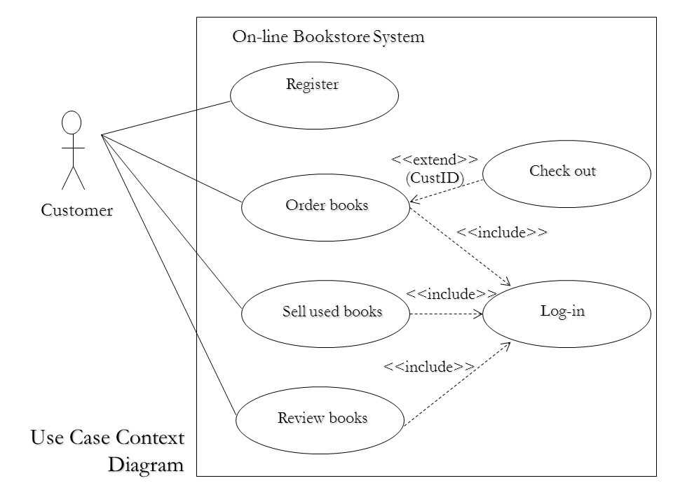
- Online Shopping: In an online shopping system, the “Place Order” use case would require the behavior of the “Add to Cart” use case. The “Place Order” use case would use the “Add to Cart” use case to add items to the shopping cart before placing the order.
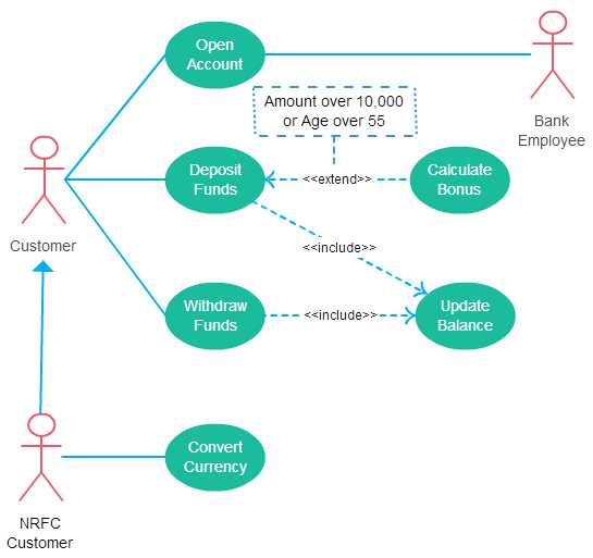
- Banking System: In a banking system, the “Transfer Funds” use case would require the behavior of the “Authenticate User” use case. The “Transfer Funds” use case would use the “Authenticate User” use case to verify the identity of the user before allowing them to transfer funds.
- Social Media: In a social media platform, the “Post Status” use case would require the behavior of the “Login” use case. The “Post Status” use case would use the “Login” use case to authenticate the user before allowing them to post a status.
The uses relationship in use case diagrams helps to illustrate the flow of behavior between different use cases and how they are connected. It provides a clear understanding of the dependencies and interactions between use cases in a system.