
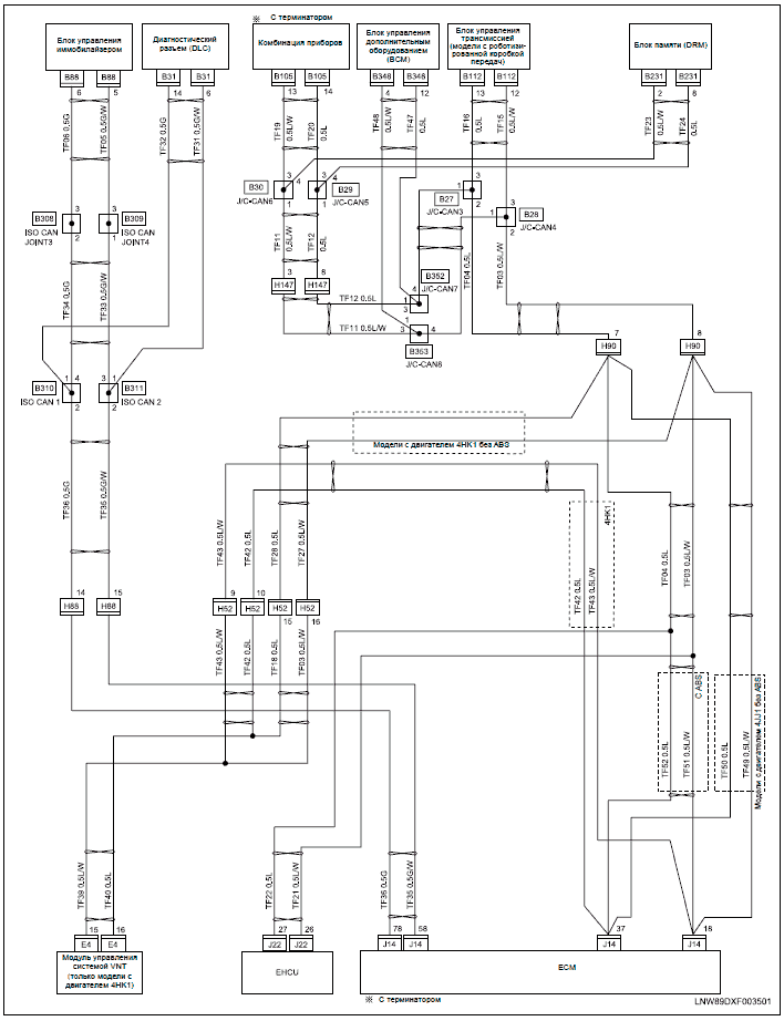
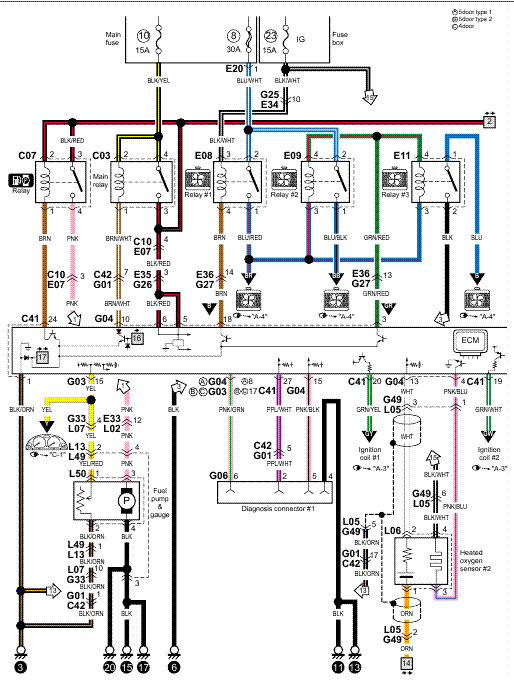
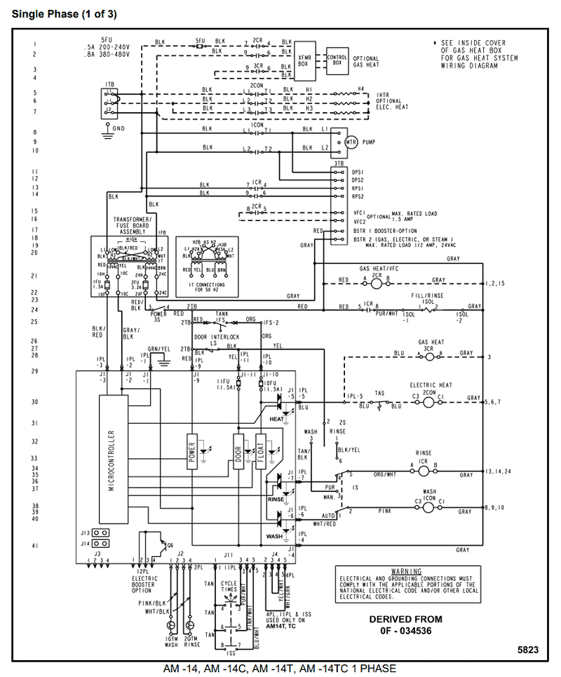
label and wiring diagram is located on the .
The TSS-EH breaks new ground in single duct VAV electric control box enclosure, with single point power. Testing Status for all Faults in Filter/Fan/Coil and VAV-Box. Cause-effect Diagram for the VAV-box Flow Rate Differing from Normal Values Under.
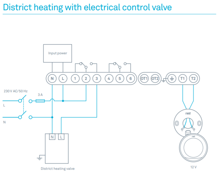
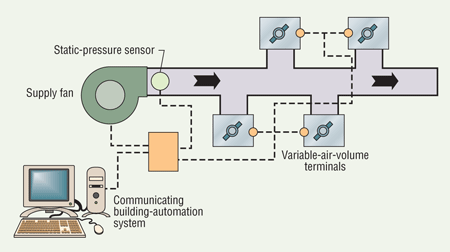
VAV terminal unit TVR-Ex with the following control components: Terminal box ExBox-SW (required if an auxiliary TE* wiring diagram. Variable air volume (VAV) is a type of heating, ventilating, and/or air-conditioning (HVAC) A common commercial application is shown in the diagram.
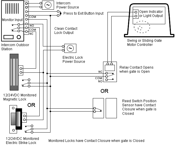
This VAV system consists of a VAV box, ductwork, and four air terminals. VAV terminal unit TVR-Ex with the following control components: Terminal box ExBox-SW (required if an auxiliary TE* wiring diagram.Single Duct terminals are the fundamental building blocks for Variable Air Volume (VAV) systems.
Their primary function is to regulate airflow to a zone, in response to zone temperature requirements. INTRO TO CONSTANT VOLUME AND VAV SYSTEMS Frank Moccio Primera Engineers.
least 1 box is full open Power Input to VFD reduced by the Cube of CFM Reduction Speed Reduced 1/2, Power to 1/8. % Include Schematic Diagrams and Points Lists in Design.

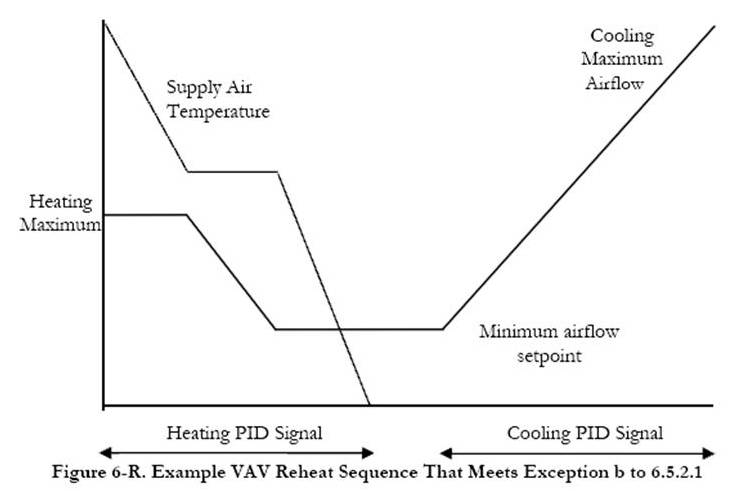
single / dual duct terminals CONTROL STRATEGIES Variable Air Volume – VAV Cooling As the room temperature increases over setpoint, the unit modulates the cold airflow from the minimum (which may be zero flow) to the maximum setting. For detailed information on specific control types, refer to the following pages in Section O.
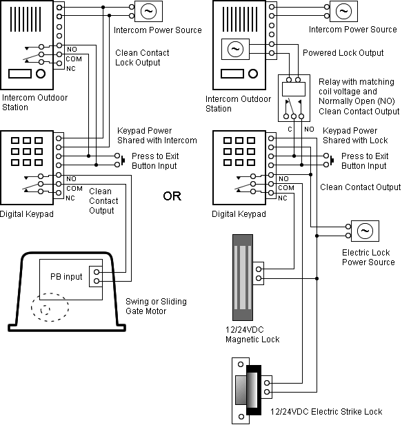
Mounting and Wiring Variable Air Volume Modular Assembly (VMA) Series Controllers Technical Bulletin 4 Key Concepts VMA Position and Orientation Consider the following when positioning and orienting the VMA: • Mount the VMA on a vertical and flat surface where it functions best, such as the side of the VAV box. vav box control sequence w/deadband vav box control sequence no deadband vav box control sequence w/deadband supplemental heat sp fe % % % % reheat flow vav air flow vav air flow vav air flow reheat flow reheat flow supp flow reheat flow a.
upon fall in space temperature the vav damper will modulate to minimum position. b.
upon.Variable air volume – WikipediaVariable air volume – Wikipedia