For smooth maintenance of the electrical system in vintage VW cars, it’s crucial to familiarize yourself with the components responsible for power distribution. Identifying which connections are linked to each function can prevent unnecessary repairs and save time during troubleshooting.
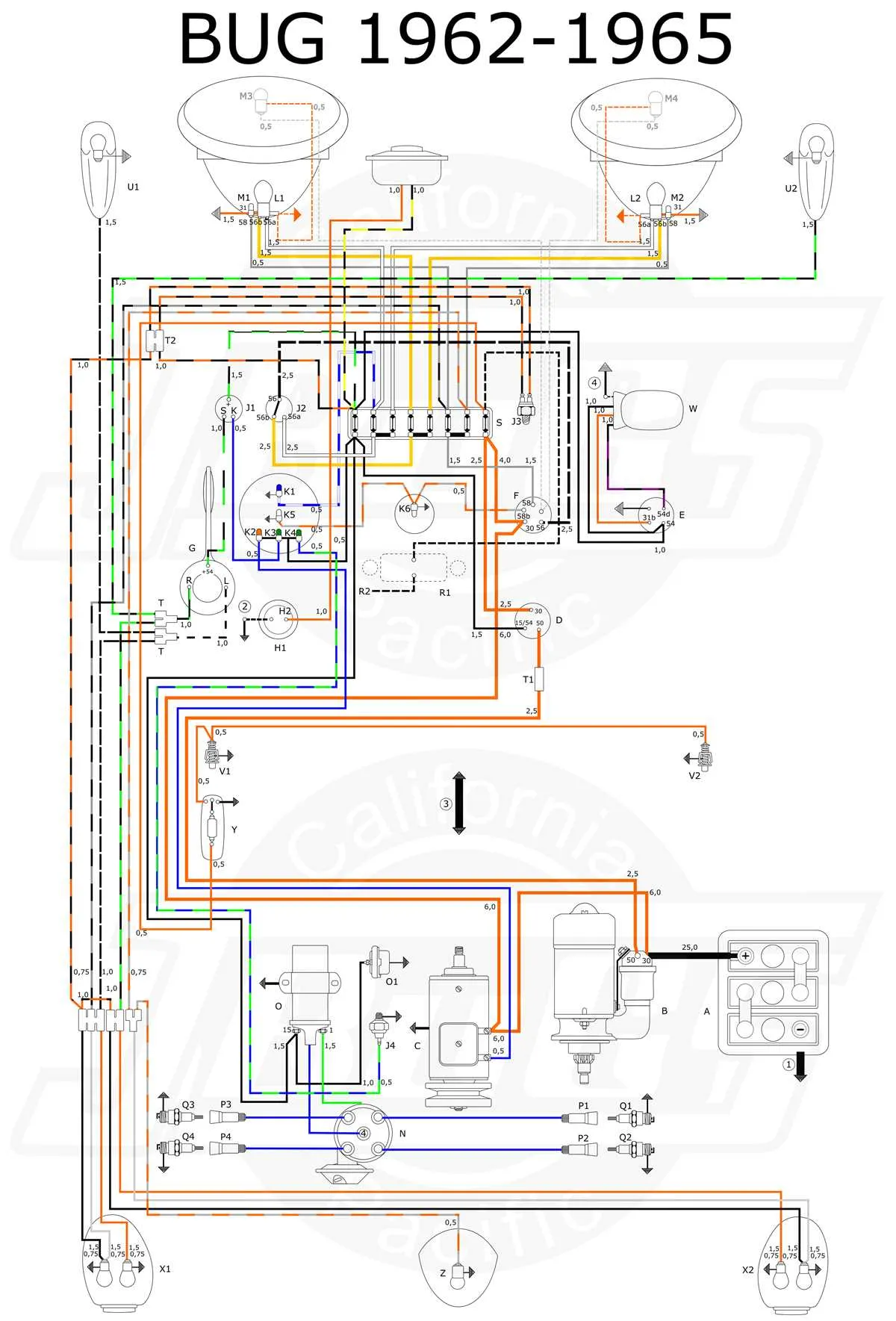
When examining the central unit that manages circuit connections, focus on the location of each terminal and its specific role in ensuring proper current flow. In older models, these units can sometimes experience wear, so a comprehensive understanding of the wire arrangements and their corresponding functions is essential for effective repairs.
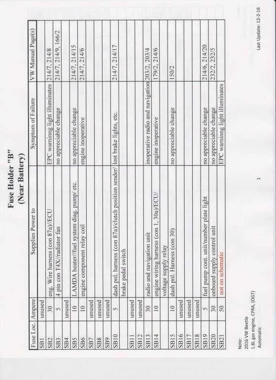
Ensure that each wire’s position is accurately recorded to avoid any misconnection during repairs. Special attention should be given to those circuits that control vital car systems such as lighting, ignition, and engine electronics. If you’re not familiar with this setup, a reference chart showing the specific locations and functions of each terminal is invaluable.
Proper diagnostics will require verifying the integrity of each connection, particularly for the older cars where corrosion or loose wires might cause intermittent issues. Once the setup is fully understood, managing these connections becomes significantly easier, and troubleshooting becomes more intuitive.
Electrical System Overview

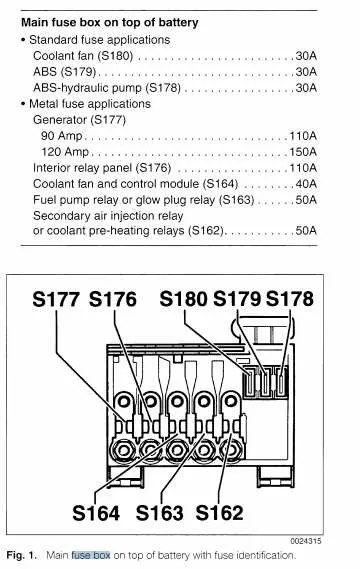
For reliable vehicle performance, identifying the locations of electrical components is crucial. Below is a guide to help you pinpoint essential wiring connections in your VW car.
- Under the dashboard: A central unit for key electrical circuits. Commonly located near the driver’s side, ensuring access to essential functions like lighting and heating.
- Engine compartment: A secondary setup to manage components like the alternator, ignition, and relay system.
Follow these steps for identification:
- Locate the central electrical unit near the driver’s seat for easy access to lighting and climate controls.
- Identify the terminal connections and ensure they are properly secured to avoid electrical failures.
- Inspect the relays and connectors for visible wear or damage. Replacing faulty components ensures uninterrupted power flow.
For troubleshooting, check the connection points between the engine and interior units. This ensures that both high-power and low-power systems are running without issues. Be sure to examine the condition of each wire and connector, replacing any that are corroded or damaged.
Identifying the Electrical Component Locations in Different VW Models

In the 1960s models, the primary panel is located under the dashboard on the driver’s side. It is often necessary to remove the cover beneath the steering wheel to access the connections. Check the area above the pedals if the compartment is not immediately visible.
For 1970s versions, the assembly tends to be found beneath the dashboard, near the footwell area. You might have to unscrew a small cover plate to reach the connections. Some versions from this era also include a secondary unit near the battery in the rear compartment.
The 1980s models commonly feature the electrical setup behind the glove compartment. You may need to pull the compartment out to gain access. Look for any fasteners or clips securing the cover, which can sometimes be hidden under a felt lining.
In the 1990s series, the location shifted to a more central position, often just beneath the driver’s seat. For easier access, the seat might need to be adjusted or moved forward, and the cover should come off with minimal effort.
For the most recent variants, the unit is often placed inside the cabin near the steering column, but its exact placement can vary based on the specific year and model. Checking the owner’s manual is recommended to find precise instructions for each variant.
How to Troubleshoot Common Electrical Panel Issues in a VW Vehicle
Start by checking the electrical connections for corrosion or loose terminals. Tighten any connections that feel insecure and clean any that show signs of rust. A quick cleaning with electrical contact cleaner can resolve many minor issues.
If certain components are not working, identify the corresponding relay or circuit. Inspect the fuses related to malfunctioning elements for any signs of damage or wear. Replacing blown fuses can immediately restore functionality to affected systems.
For recurring electrical failures, inspect the wiring leading to and from the panel. Look for any frays or breaks in the insulation. Faulty wiring can result in intermittent power loss, which is often misattributed to other components.
If power interruptions are persistent, test the ground connections. A loose or corroded ground can cause unstable or fluctuating electrical flow, leading to a variety of system malfunctions.
Pay attention to the control unit or relay box for signs of overheating or short circuits. If components feel warm to the touch, it could indicate a problem with internal circuits or an overload in the system.
For issues involving lights or signals, verify that the relevant relays are functioning properly. Swap them with known good ones to test whether the issue is due to a malfunctioning relay.
After addressing immediate issues, ensure the entire electrical network is properly grounded and insulated to prevent further damage from environmental factors like moisture or temperature extremes.
Step-by-Step Guide to Replacing Electrical Components in a VW Vehicle

Start by locating the central electrical panel inside your car. It is typically located under the dashboard or in the engine compartment, depending on the model year. Once found, ensure the vehicle is turned off and the key is removed.
Using a small flathead screwdriver, gently pry the cover open. Be cautious not to damage any clips or fasteners. Once the cover is removed, you will see a series of individual connectors that control various systems such as lights, air conditioning, and ignition.
Identify the malfunctioning component by checking for any visible signs of damage, like burnt areas or discoloration. You can also refer to the panel’s manual for the exact location of each connector.
Carefully pull the faulty connector out of its socket. Make sure to grip it firmly to avoid breaking the fragile pins. When removing, avoid touching any exposed wires to prevent accidental short circuits.
Replace the damaged component with a new one of the exact specifications. Check the part number to ensure compatibility with your vehicle model.
Before reassembling, test the newly installed connector by turning on the ignition and activating the corresponding system. If it functions correctly, proceed to close the panel and reattach the cover.
Always dispose of any broken components responsibly, and regularly check the condition of these parts to avoid future issues.