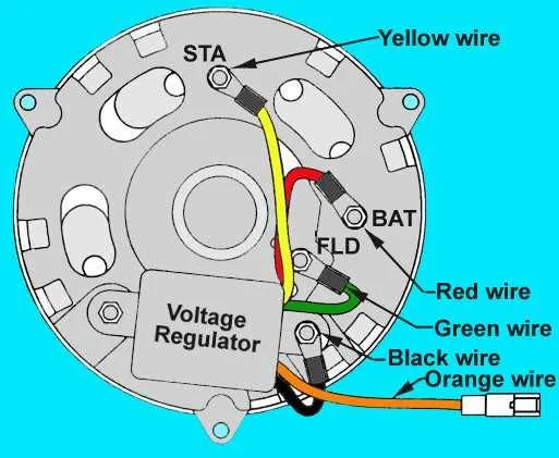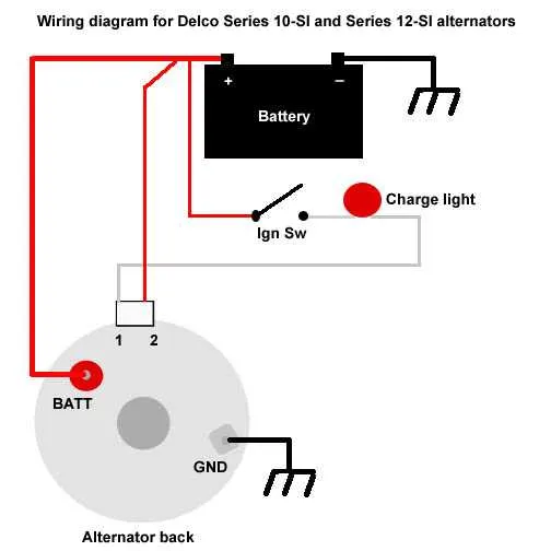
Start by identifying the three essential terminals on the unit: the field, output, and ground connections. Each terminal plays a crucial role in maintaining stable power generation and distribution within the system. The field terminal is typically linked to the voltage regulator, ensuring proper excitation control for the system.
The output terminal, also known as the power lead, carries the generated electricity to the battery or electrical load. Make sure it is securely connected to avoid any risk of voltage drops. Lastly, the ground terminal serves as the return path, completing the electrical circuit and preventing system malfunction.
For a seamless setup, consider using color-coded connections to easily differentiate between each terminal. This reduces the chances of wiring errors, ensuring both safety and efficiency during installation or maintenance. Properly tightening all connectors is essential to avoid overheating or electrical shorts during operation.
Remember that precise alignment between components is vital for performance. Make sure that the output is directed towards the battery or load and that the voltage regulator is calibrated correctly to handle system demands.
Connecting a 3-Terminal Generator System
To ensure proper functionality of a 3-terminal charging unit, connect the terminals as follows:
Terminal 1: Connect to the positive side of the battery. This terminal will carry the voltage output to charge the system.
Terminal 2: Attach this to the ground or negative side, completing the circuit and enabling proper current flow to stabilize the charge.
Terminal 3: Link this to the voltage regulator or a control mechanism. This terminal regulates the output voltage and prevents overcharging by maintaining the set voltage level.
Note: Proper grounding and secure connections are crucial for preventing electrical issues and ensuring efficient operation of the system. Always double-check connections before powering up the unit.
How to Connect the Three Wires of a 3-Wire Alternator

Start by identifying the three leads: the main output, ground, and excitation signal. Each plays a crucial role in proper functionality. Connect the output terminal to the battery or distribution block. This is where the electrical current will flow to power your system.
Next, the ground connection must be securely fastened to the vehicle chassis or a solid metal part that provides a low-resistance return path to the negative terminal of the battery. Make sure the ground point is free of rust and paint to ensure a reliable connection.
The excitation lead controls the voltage regulation and requires connection to a switched power source. This enables the regulator to control the voltage output when the engine is running. Ensure the excitation wire is routed correctly, avoiding interference from high-heat areas like exhaust pipes or engine blocks.
Always use properly rated connectors and check the tightness of each connection. Loose or corroded contacts can lead to voltage fluctuations and component failure. Verify that each lead is free from damage and has good insulation to prevent short circuits.
Once all connections are made, perform a test by starting the engine and checking the voltage at the output terminal. The voltage should be around 13.8-14.4 volts, depending on the system’s specifications. If voltage is inconsistent, recheck the excitation and ground connections.
Understanding the Role of the Field, Ground, and Battery Cables in a 3-Wire System

Field connection: The field terminal controls the voltage regulation in the system. It connects to the voltage regulator, which adjusts the electrical current flowing through the field coil. This process ensures that the system generates the correct output voltage based on the load and operational conditions. A stable connection to the field terminal is essential for maintaining the proper voltage levels.
Ground connection: The ground terminal is crucial for completing the circuit and preventing electrical feedback. It provides a return path for the current, ensuring that excess voltage is safely redirected. Poor grounding can lead to fluctuating output or even damage to the components due to improper discharge.
Battery terminal: The battery terminal serves as the source of power to charge the battery. It supplies current to replenish the charge that is used by the vehicle’s electrical systems. A solid connection here ensures that the battery maintains its charge, keeping all electrical systems operational during both idle and active periods.
Troubleshooting Common Wiring Issues in 3-Wire Alternator Systems
Start by checking the ground connection. A loose or corroded ground can cause inconsistent charging or failure to charge at all. Ensure the connection is clean, tight, and free from rust.
Next, inspect the voltage regulator. A malfunctioning regulator often leads to improper voltage output. Test it with a multimeter to verify that the correct voltage is being produced based on your vehicle’s system requirements.
Pay close attention to the charging terminal. Corrosion or a poor connection here can prevent sufficient current from being delivered to the battery. Clean any dirt or corrosion and check the terminal’s tightness.
Examine the connection between the stator and the regulator. A loose or broken connection here can cause the system to undercharge. If the stator is damaged, it may need to be replaced.
- Check for any loose or frayed connectors, especially near the regulator.
- Test the continuity of the stator coil, as a short or open coil can disrupt the charging process.
- If voltage fluctuations occur, it may indicate a failing regulator or wiring issues in the system.
Finally, inspect the fuse and any associated components. A blown fuse often causes a complete failure in charging. Replace any damaged fuses and verify the amperage rating matches the specifications.
Systematic testing and component replacement are crucial. If unsure about any part’s integrity, consult the vehicle’s manual or seek professional assistance.