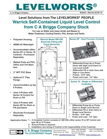
Warrick® controls are available in many different designs and sensitivity .. Wiring. Series 16M & 16HM.
Series 16DM. Note: For single level service, use “H” . Engineered for general purpose single-level or differential applications, these controls have spade terminals for easy wiring and provide sensitivities up to 1.
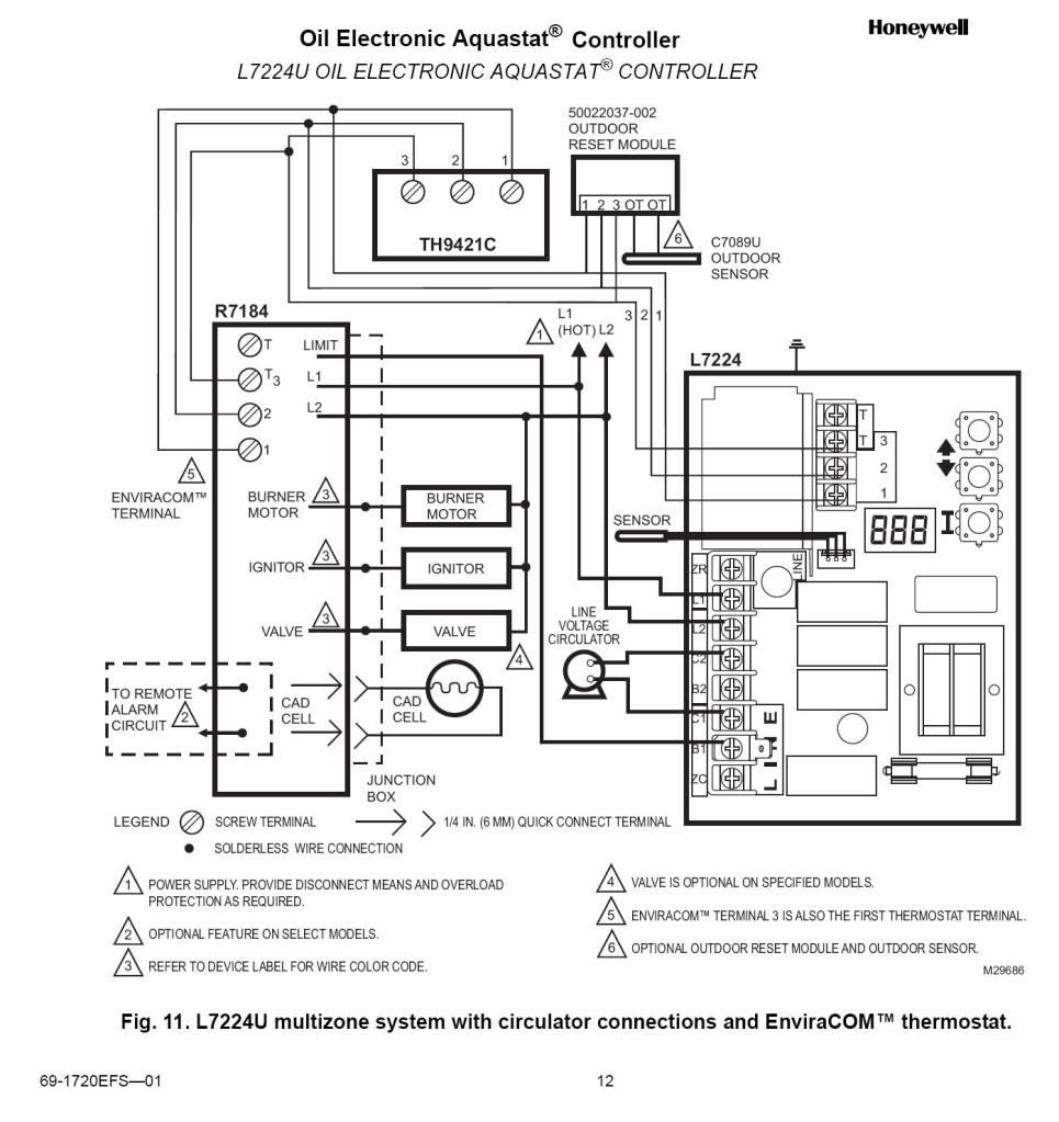
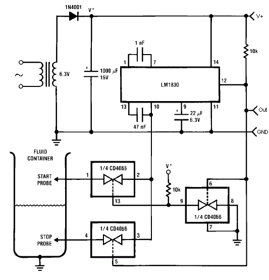
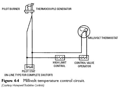
Wire control per diagram, following N.E.C. and local codes.
Use appropriately Warrick® Series 26H Controls. Installation and Wiring Diagram. Automatic.
Warrick Liquid Level Sensors are available in single- and multi-probe models and with a variety of fittings. The versatility of the Warrick design makes these. 3.
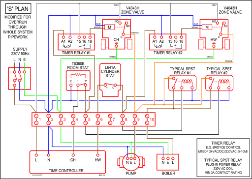
Wire the control device(s) to the Series 27 relay as shown in the specific application wiring diagram in this bulletin. A separate rigid metallic conduit should be.Wiring Diagram Operation. Direct Mode- Single Level Service: When the liquid rises to the electrode on terminal 3, the control energizes, changing state of the load contacts.
(LED will be lit) The control remains ener- gized until the liquid level recedes below electrode on terminal 3. U.L. “Limit Control” U.L.
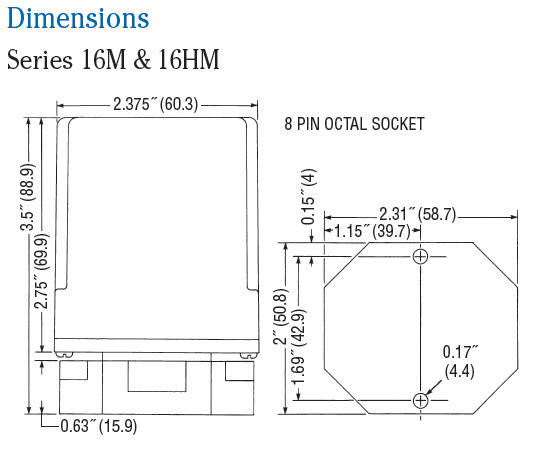
“Motor Control” One of Warrick’s fi rst products, Series 1 electromechanical controls offer 2 or 3 pole output contacts with 16 amp rating. Warrick Series 3C – Short Probes External Mount Side Chamber. Pipe tappings provide connection to the side of boilers and pressure vessels to equalize the level in the chamber with the level in the vessel.
Warrick Series 3K Long External Mount Side Chamber Fittings contain up to 4 probes and accommodate probes from /4˝ to 13˝ in length. Additional tappings are available for tricocks and gauges. Warrick® Conductivity level control systems rely on the liquid level sensing capability of probes (electrodes) that are housed inside fittings designed to accommodate one or more probes.
The concept is simple: take advantage of a liquid’s conductive properties to complete a circuit and cause a . Single Point Inverse Mode Control – Uses G and H electrodes.
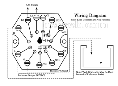
As soon as this control has power connected to L1 and L2, the control should energize. With a jumper wire, jump from terminal G to Terminal H – the control should de-energize.
Remove the jumper. The control should energize.Warrick Troubleshooting GuideWarrick Controls Wiring Diagrams | Wiring Library