WHIPPLE CHARGER INSTALLATION INSTRUCTIONS. FOR KIT air motor ( oval 4 wire plugs) and the throttle position sensor (round 3 wire plug) on the Unplug wire harness from EGR valve, remove two mounting bolts and remove EGR. A color PDF of this manual is available, email .
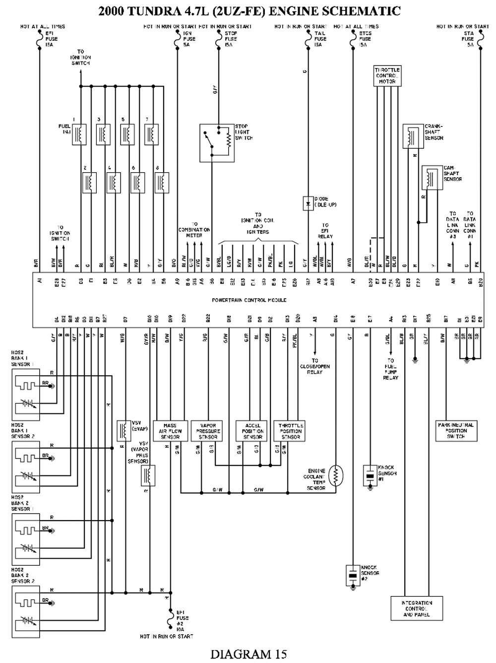
The blue wire is your signal wire , the TPS is a 5v sensor. The ECU is controlling idle mainly by.
Installation Manual: Mustang Supercharger System(B1R8) . Before installing your Whipple Ford Racing Supercharger Kit, complete the ..
Reposition the knock sensor wires by loosening the (2) 8mm bolts (10mm socket). These will be useful for securing the wiring harness away from the installation . Disconnect the factory MAP sensor on the back of the intake manifold by pulling.
Installation Manual: Mustang Supercharger System(B1R8) . Before installing your Whipple Ford Racing Supercharger Kit, complete the ..
Reposition the knock sensor wires by loosening the (2) 8mm bolts (10mm socket).Install the extra fuel injectors into the Whipple intake and plug in the wires from the Whipple computer. Install the Whipple air plenum and run it over to the stock air box and MAF sensor. Install the new K&N air filter into the stock air box.
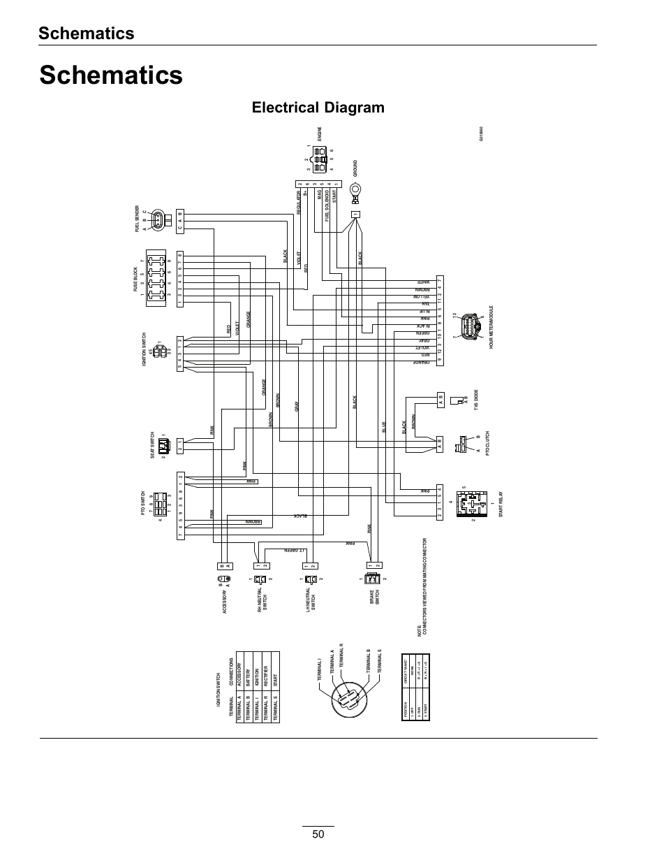
MAFS Mass Air Flow Sensor PCM Powertrain Control Module (a.k.a. ECM, ECU, PCU, EEC) PCV Positive Crankcase Ventilation TPS Throttle Position Sensor VMV Vapor Management Valve (aka Canister Purge Valve) Breakout Point A place in an electrical harness where the wiring for an individual component leaves.
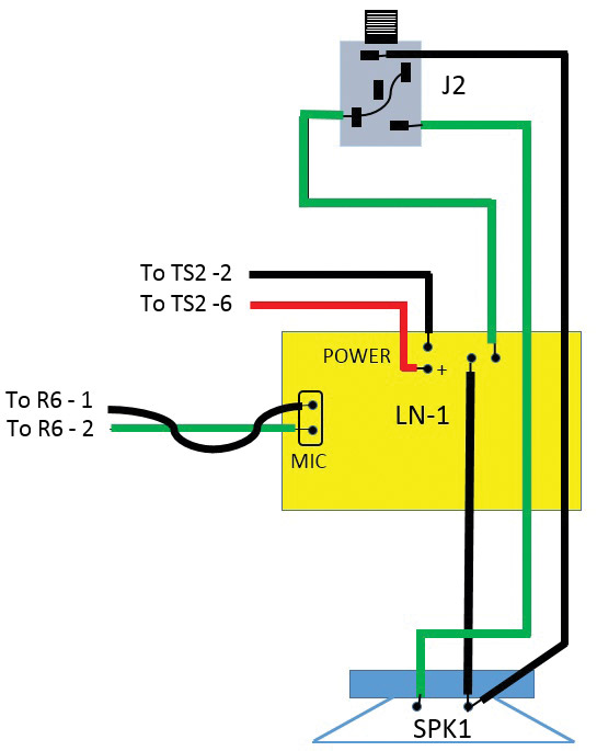
Project Nitemare Supercharged LQ4 Well this project is going to take the rwhp vortec L dark nite project and go the next step with it and slap a whipple supercharger and custom 3″ pulley which ended up making lbs of boost on the dyno. WHIPPLE CHARGER INSTALLATION INSTRUCTIONS / MAGNUM MPI STAGE 1 This product is intended fo r use on STOCK, The TPS is a 5v sensor. The blue wire is the signal wire.
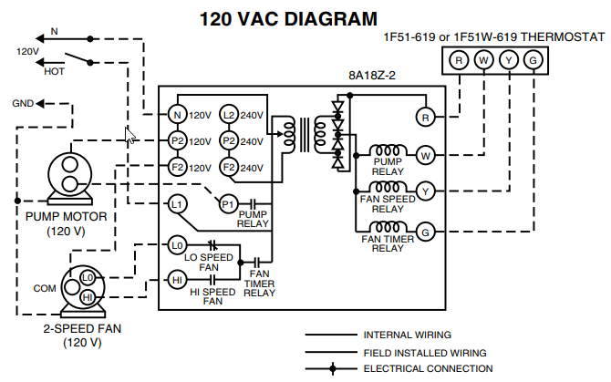
Follow the wire diagram at the end of the manual for converting. 4. Supercharger By-pass system. These will be useful for securing the wiring harness away from the installation area as directed in the Illustrated Whipple Supercharger Kit and ensure all items are present and undamaged. 6.
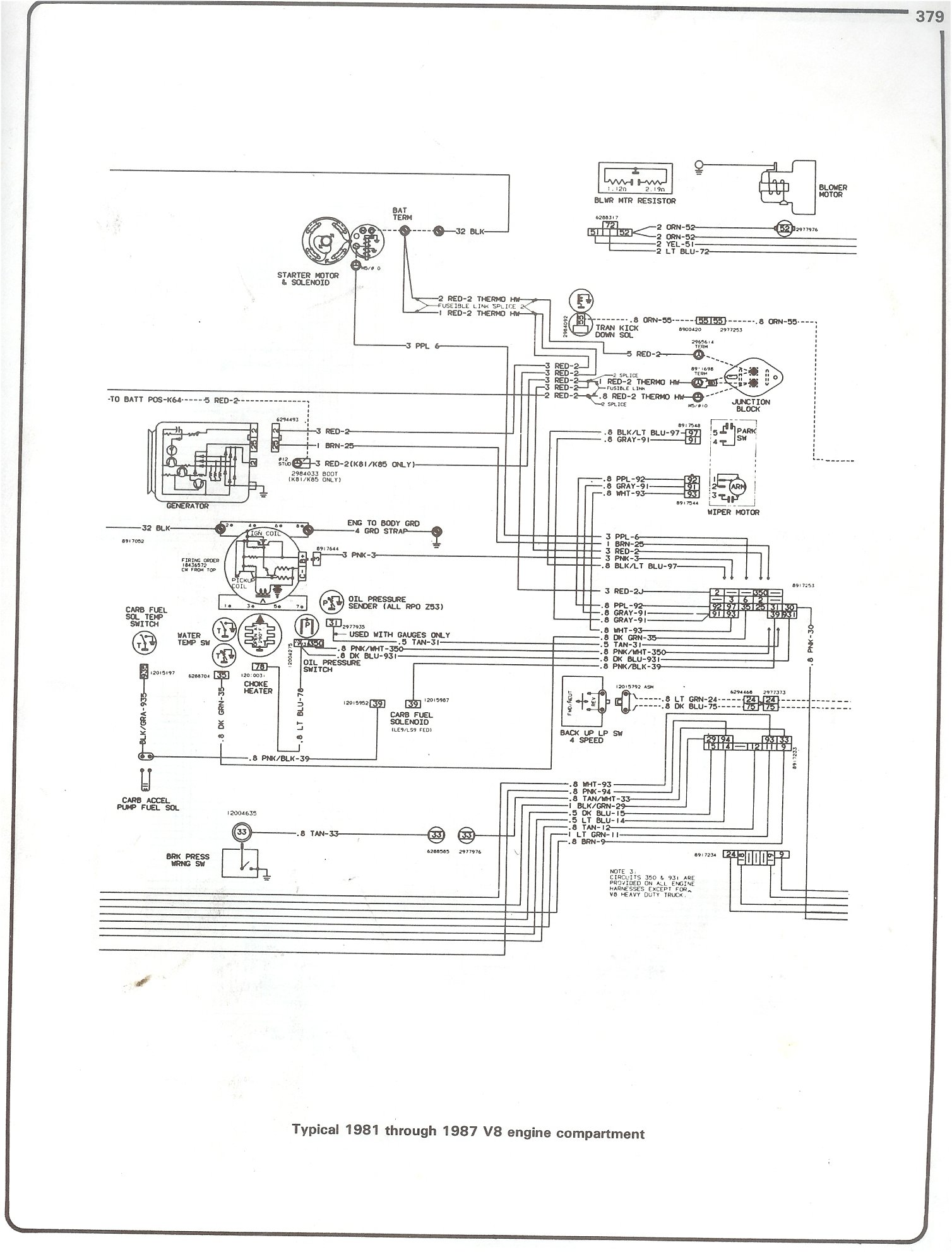
Mass Air Flow Sensor element. Carefully pull red tab out, squeeze the connector and then pull the.Dodge Charger L Supercharger SystemProject Nitemare Supercharged LQ4 – Harris Performance
