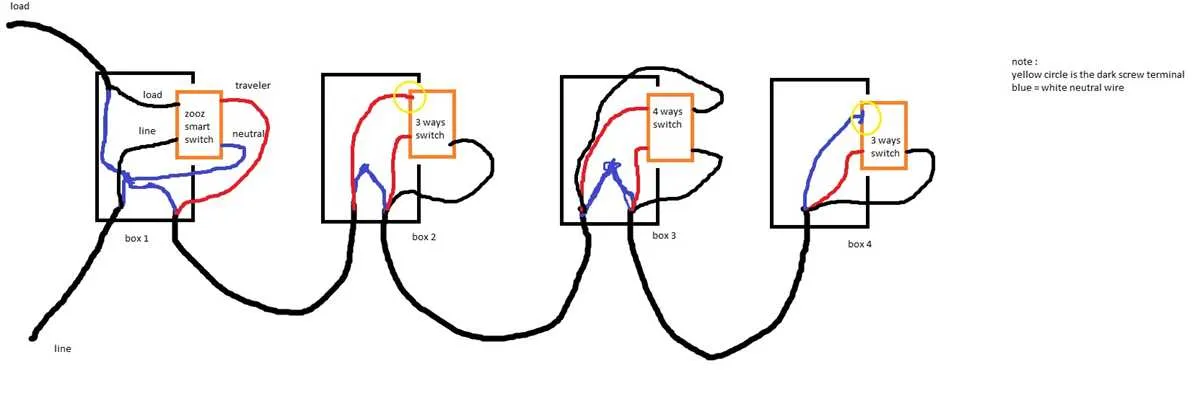
To correctly set up a 5-terminal toggle, start by identifying the common terminal, which serves as the main input point for the circuit. Ensure the traveler leads are properly connected to allow multiple control locations to function seamlessly. Miswiring traveler wires often leads to malfunction or inconsistent operation.
Use a multimeter to verify continuity between terminals before finalizing connections. The common point must connect to the power source or load depending on the specific application. Labeling each conductor helps avoid confusion during installation and future maintenance.
When controlling lighting or other devices from several spots, the correct linkage of intermediate contacts ensures smooth switching. Avoid reversing traveler wires, as this disrupts signal flow and can cause flickering or failure. Secure all connections with proper terminals and insulated caps to prevent shorts.
Identifying Terminals and Wires on a 5-Position Control Device
Start by locating the common terminal, usually marked with a different color such as black or copper. This is the primary connection point for the incoming power source or the load line.
Next, distinguish traveler contacts–these are multiple terminals arranged in pairs and typically connected with colored wires like red or brass. Their role is to link intermediate toggles, allowing current to pass through different paths.
Look for a ground terminal often identified by a green screw or a bare copper wire. This ensures safety by connecting the frame or metal parts to earth ground.
Wires connected to these terminals must be tested for continuity using a multimeter before installation to verify correct identification and avoid cross connections.
Note the terminal layout varies by manufacturer but common patterns include a central common terminal flanked by traveler points on each side. Carefully read any stamped labels or markings near each contact.
Use color coding as a guide–black or dark wires are generally hot or common, reds are travelers, and green or bare wires are grounding. Confirm with testing since color standards can differ.
Label each wire upon disconnection to maintain clarity during reassembly, especially in complex multi-position setups.
Step-by-step connection process for a 5-contact selector setup

- Disconnect power from the entire circuit to prevent accidental shorts or electric shock.
- Identify and label each traveler conductor and terminal on the devices–typically, two inputs and three outputs are involved.
- Mount all control modules securely in their enclosures before making any connections.
- Connect the common line (typically the hot feed) to the designated central post of the first control element.
- Run two traveler conductors between each controller in the chain: from unit A to B, B to C, and so on.
- Attach these travelers to the matching screw terminals (usually brass or silver-colored) without crossing paths.
- Link the final device’s output pole directly to the load’s input terminal.
- Secure all ground conductors to the grounding screws inside each box, ensuring continuity.
- Double-check continuity with a multimeter to ensure no crossed paths or open connections.
- Restore power and verify proper operation by toggling the selectors in various combinations to test consistency of the control logic.
Use color-coded conductors to simplify future troubleshooting and maintain a clear schematic record for all junctions involved in this configuration.
Troubleshooting common connection issues with 5-position selectors
Start by verifying continuity between terminals using a multimeter. Rotate the selector through each position and confirm that expected contact points close properly without resistance. Unexpected open lines often indicate mechanical failure inside the rotary body.
Inspect solder joints or push-fit terminals for cold connections or corrosion. Oxidized points can intermittently fail under load, especially in older assemblies or those exposed to humidity.
Cross-check color-coded leads against the intended control logic. Misaligned conductors often result from misreading layout schematics or mirrored component mounting.
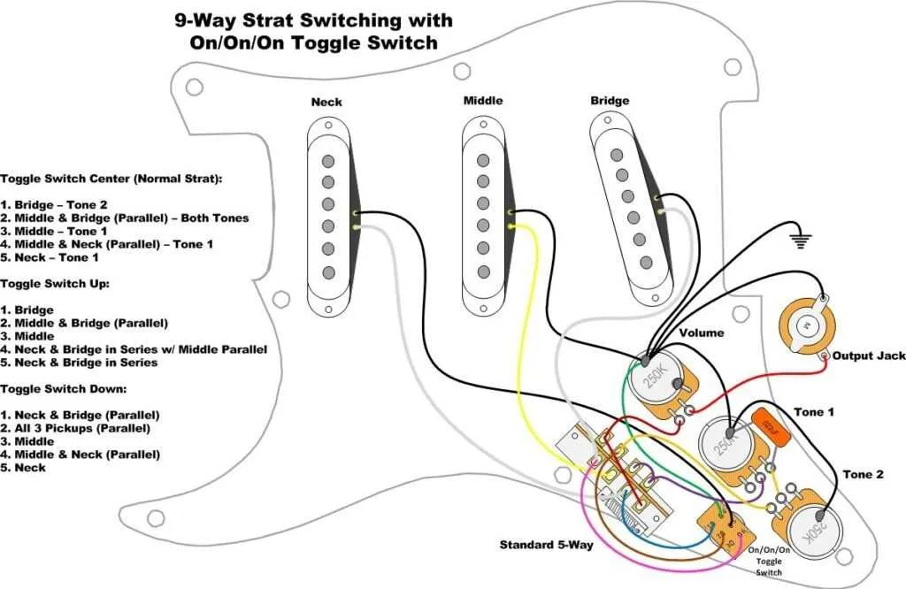
For setups with coil taps (e.g., humbucker splits), test each tone position while injecting an audio signal. Signal dropout or buzz may trace back to grounding faults or reversed phase lines between output lugs and pickup commons.
Review shared paths between middle positions. Shared terminals can accidentally short if excess wire strands or stray solder bridge adjacent lugs. Use magnification to rule out micro shorts.
Check for mechanical detent wear if selector slips between stops. Poor indexing can cause incomplete contact, leading to intermittent tone issues under vibration or movement.