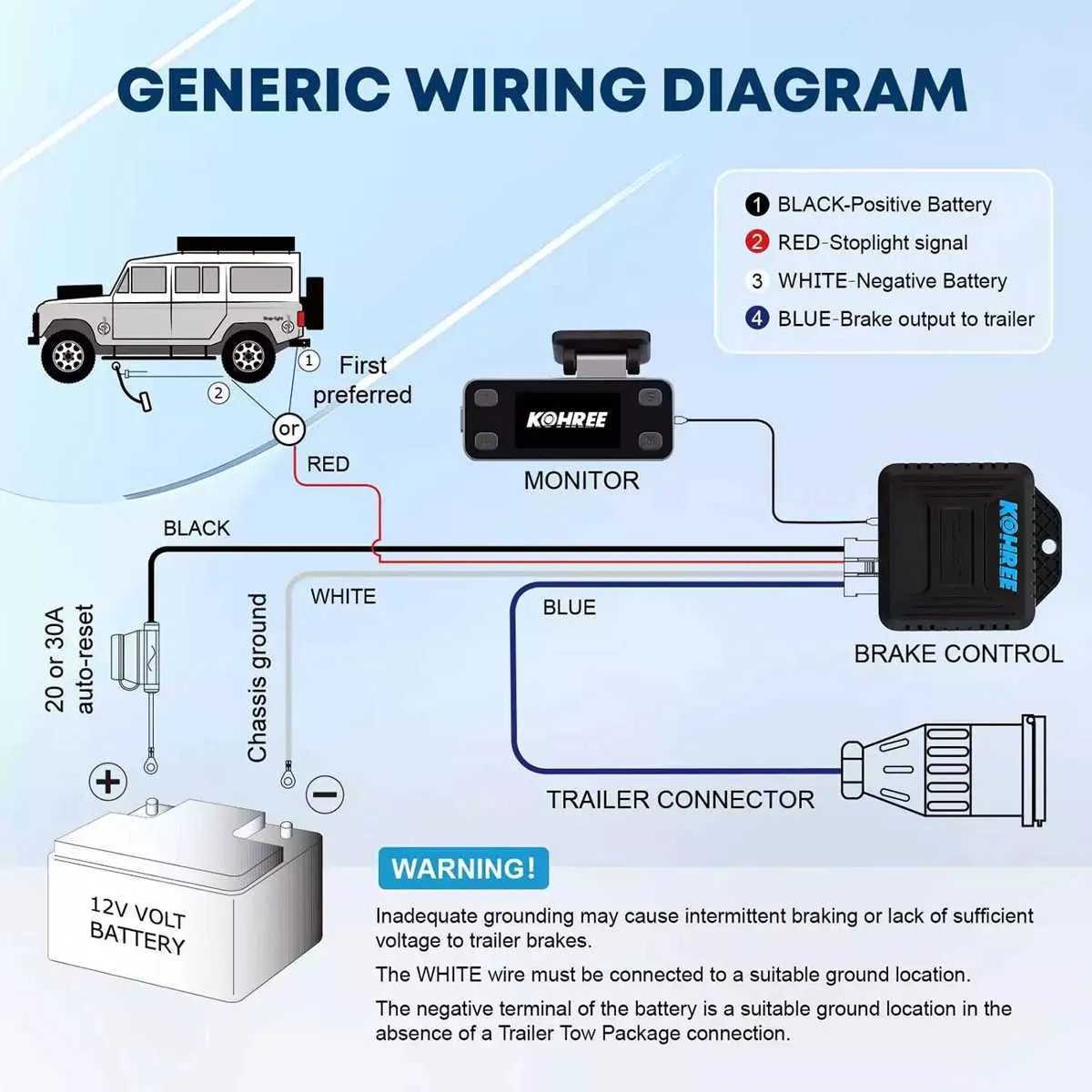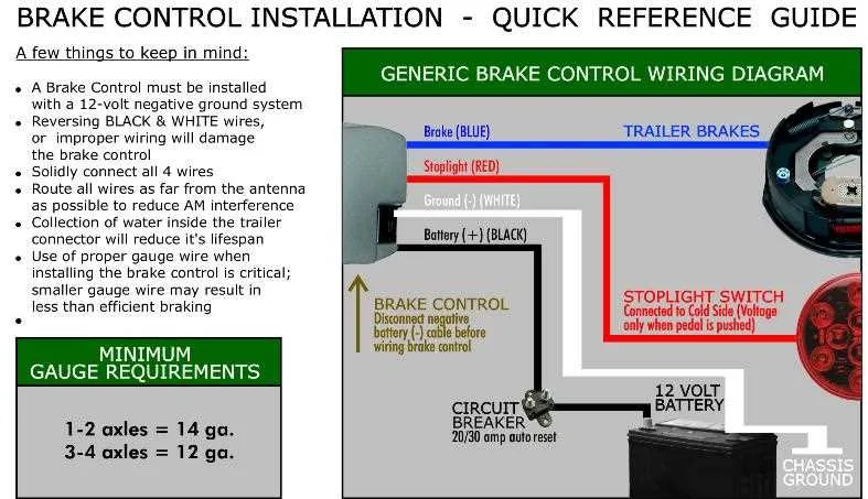
To ensure safe and effective use of a towing setup, it’s essential to connect the necessary components of the trailer’s stopping mechanism to the vehicle’s electrical system. The proper configuration involves connecting specific wires to activate the trailer’s stopping feature when needed, with each wire serving a distinct role.
First, identify the correct terminal for the activation signal from the towing vehicle. Typically, this signal is sent through a dedicated wire that interacts with the braking system of the trailer. It’s critical to use a reliable connector to avoid potential malfunctions during towing.
Second, ensure that power is properly routed to the trailer’s system from the vehicle. A direct connection to the vehicle’s electrical source must be made, with proper fusing to prevent overloading. Double-check that all connections are secure to avoid power loss or system failure.
Third, the ground wire must be firmly connected to the vehicle’s chassis to complete the circuit. Without a proper ground, the system will not function as intended, leading to ineffective performance.
Lastly, testing the setup is crucial to verify that the signal transmission from the vehicle to the trailer’s stopping feature is functioning. Always perform a test with the vehicle and trailer in a safe environment before taking the setup on the road.
Electrical Connections for Trailer Braking System
To ensure proper functioning of your trailer’s braking system, follow these pin assignments for a secure installation. First, connect the power wire to a 12V supply, typically from the vehicle’s battery, ensuring it is fused appropriately. The ground terminal should be linked to the vehicle’s chassis, establishing a reliable connection to prevent malfunctions.
The signal wire must be attached to the towing vehicle’s brake light circuit. This link allows the braking mechanism to activate when the vehicle’s brakes are engaged. The output lead should be connected to the trailer’s brakes, sending the necessary signal to engage the braking force.
Next, use a heavy-duty wire for the safety feature, ensuring it connects directly from the trailer to the towing vehicle’s electrical system. This wire should be routed separately to prevent interference with other connections. Also, verify that the output to the trailer’s brakes is sized properly for the load requirements of the towing vehicle and trailer combination.
Lastly, confirm that all terminals are securely fastened and insulated to avoid any potential short circuits. Double-check all connections and test the system to ensure the trailer brakes engage as expected during braking scenarios.
Identifying Pinout Connections
Start by ensuring you have the correct connector type, typically a 6-pin or 7-pin arrangement, depending on the model and manufacturer. Once identified, you can proceed with assigning the proper functions to each pin.
- Pin 1: Power (12V) – This pin supplies direct current from the vehicle’s battery to the device. It should be connected to a fused power source, usually a 12V DC line.
- Pin 2: Ground – The negative connection completes the circuit. Connect this to a solid ground point on the vehicle’s chassis to ensure reliable operation.
- Pin 3: Signal Input – Used to receive input from the vehicle’s braking system. It typically connects to the brake light switch to signal activation.
- Pin 4: Signal Output – Sends the signal to the towing vehicle’s electric braking system. This pin ensures that power is distributed accordingly to the trailer’s braking system.
- Pin 5: Aux Power – This pin is often used to provide power to additional accessories or to control a secondary circuit.
- Pin 6: Manual Activation – This connection allows manual activation of the braking system, usually through a lever or button in the cab of the vehicle.
- Pin 7: Battery Charge – In some configurations, this pin provides charging power to the trailer’s battery when connected.
Double-check the configuration against the manufacturer’s manual to confirm pin assignments, as some variations exist between models.
Step-by-Step Guide to Connecting a Trailer’s Stopping System to Your Vehicle

Start by identifying the correct power source in your vehicle, typically the fuse box or the battery. You’ll need to connect a 12V power lead to the appropriate terminal to supply constant power.
Next, locate the emergency stop wire. This should be connected to the vehicle’s brake light circuit. It ensures that the trailer’s stopping system activates when the vehicle’s brakes are engaged.
Attach the ground wire to a clean, unpainted metal surface on the vehicle’s frame. This is crucial for completing the circuit and ensuring proper function.
Now, connect the signal wire to the vehicle’s turn signal circuit. This allows the trailer’s lights to mirror the vehicle’s turn signals. Test the connection by signaling left and right.
Link the activation wire to a switch within easy reach of the driver. This allows for manual control of the trailer’s stopping system when necessary.
Once all connections are in place, test the system. Check that all connections are secure, and verify the vehicle’s lights and the trailer’s system are functioning as expected.
Common Electrical Mistakes and How to Avoid Them
Ensure proper grounding: Always connect the ground wire to a solid metal part of the chassis. A poor ground connection can lead to malfunctioning of the entire system, causing erratic performance or even complete failure. Verify the ground connection with a multimeter for continuity.
Choose the correct wire size: Using wires that are too thin for the amperage can cause overheating and potentially lead to a fire hazard. Always check the specifications and use wires that meet or exceed the recommended gauge based on the current draw of your equipment.
Check the polarity: Reversing positive and negative connections is a common mistake. Always double-check the polarity before making connections. Incorrect polarity can damage the electronics and even prevent the system from working altogether.
Avoid excessive wire length: Longer wires introduce more resistance, which can result in voltage drops. Always cut wires to the appropriate length and avoid unnecessary slack. This ensures better performance and minimizes potential issues.
Secure connections properly: Loose connections are a major cause of intermittent operation. Use proper terminals and ensure all connections are tight and secure. Consider using soldering for a more durable and reliable connection when possible.
Use proper fuses: Always include a fuse rated correctly for the system. An undersized fuse can blow too easily, while an oversized one may fail to protect the system in case of a short circuit. Always match the fuse rating with the current requirements.
Test before final installation: Before securing everything in place, test all connections and the entire setup. This will help identify any errors that may have occurred during the installation, allowing you to make corrections before finalizing the project.