When troubleshooting or upgrading your home’s heating system, a clear understanding of how each component interacts is crucial. The schematic of a boiler system reveals key details that help in proper installation, maintenance, and repair. Identifying where the heat source, expansion valves, pressure relief, and pipe connections are located ensures you can diagnose issues faster and with precision.
Efficient insulation around pipes and the primary unit itself is essential for energy conservation. Ensure that the circulation flow is unobstructed and that valves, especially the pressure-regulating valve, are correctly calibrated for optimal performance. Check all connections for leaks and ensure the system is purged of any air pockets, which can impair heating efficiency.
The heating element should be monitored for wear and tear. If it’s underperforming, it may signal the need for cleaning or replacement. Ensuring the electrical components are properly wired will prevent unnecessary breakdowns, especially during peak demand times.
Familiarity with the unit’s schematic layout will also enable you to adjust settings manually when needed. Knowing how to quickly isolate and replace faulty parts can save time and money when dealing with issues such as insufficient heat output or sudden failures.
Understanding the Heating System Blueprint

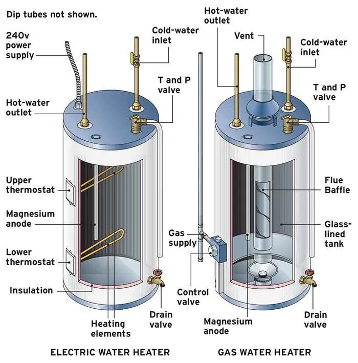
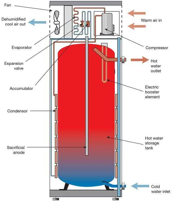
The core function of a residential heating unit is to efficiently store and distribute heated liquid. A proper schematic can help pinpoint key components like the heating element, thermostat, and pressure relief valve, all crucial for safe and effective operation. Ensure that the temperature and pressure settings on the unit align with manufacturer recommendations to avoid overpressure situations, which could lead to malfunction or even rupture.
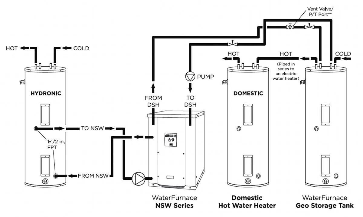
Familiarize yourself with the circulation system, including inlet and outlet pipes, as well as the connections between the primary chamber and auxiliary components. A clear representation of this system ensures easy identification of potential issues such as leaks, blockages, or faulty valves. Additionally, understanding the configuration of insulation around the container can improve energy efficiency and reduce heat loss, enhancing the system’s overall performance.
For proper maintenance, regular inspection of the safety features, including the thermostat and the temperature pressure relief valve (TPRV), is essential. These devices regulate internal pressure and prevent overheating, ensuring that the unit operates within safe limits. An effective inspection process should also verify the integrity of the anode rod, which prevents corrosion in the metal container by attracting corrosive elements within the liquid.
Efficient operation depends not just on the elements themselves but also on the proper installation of associated piping and venting systems. Pay close attention to the layout of exhaust outlets to ensure unobstructed venting, which prevents the buildup of harmful gases and minimizes wear on the system.
Understanding the Components of a Heating Reservoir
Knowing the essential parts of a heating reservoir allows for better maintenance and troubleshooting. Below are key components to focus on:
- Thermostat: Controls the temperature of the fluid inside. Ensure it’s set to the desired level for optimal performance.
- Heating Element: Converts electrical energy into heat. It’s crucial to inspect it regularly for any buildup or wear, as this can impact efficiency.
- Insulation: A thick layer around the exterior helps retain heat. Over time, this may degrade, so consider replacing it for energy conservation.
- Pressure Relief Valve: Prevents the system from building up excessive pressure. It should be checked annually for proper functionality to avoid potential failures.
- Anode Rod: Prevents corrosion by attracting minerals in the liquid. Replace it when it shows signs of wear to extend the lifespan of the unit.
- Drain Valve: Used for emptying the reservoir. Regularly flush the system to eliminate sediment buildup, which can decrease efficiency.
- Inlet and Outlet Pipes: The entry and exit points for fluid. Ensure they’re properly insulated and free of blockages to avoid energy loss.
Regular maintenance and checking these parts ensures optimal function and longevity of your heating reservoir. Proactive replacement of worn-out components can prevent costly repairs later.
How to Read a Heater Wiring and Piping Blueprint

Start by identifying the power supply connection points. These are typically represented by a pair of terminals labeled L (live) and N (neutral). The live wire connects to the heating element, while the neutral returns to the circuit panel.
Next, examine the thermostat connections. These are usually shown with two wires attached to a switch. The diagram will indicate whether the thermostat is wired in series or parallel with the heating element.
For the plumbing aspect, locate the inlet and outlet ports. The inlet, usually marked with an arrow pointing towards the unit, connects to the cold water supply. The outlet, with an arrow pointing away, delivers heated fluid to the rest of the system.
The presence of a safety valve is crucial. Look for a relief valve symbol, often located near the top or side of the vessel, which is connected to the discharge line. This valve ensures that pressure doesn’t build up to dangerous levels.
Pay attention to any sensors or additional elements, such as the anode rod. These may be represented with a small circle or rod symbol and are important for corrosion prevention.
Key Tip: Always check the ground wire connection, especially if it’s indicated separately. A faulty ground can cause serious electrical issues, so make sure this is properly linked to the system’s metallic frame.
Identifying Common Issues through Heating System Schematics

Reviewing the schematic layout of a heating system can help diagnose several typical problems. Start by checking the pressure relief valve. If it’s stuck or malfunctioning, it could lead to overpressure, potentially causing leaks or failure. Look for any signs of wear or corrosion around the valve area, which can indicate repeated pressure issues.
Next, inspect the thermostat connections. A miscalibrated or faulty sensor can cause irregular temperature fluctuations. Compare the reading on the thermostat to an external thermometer to verify accuracy. If discrepancies are found, recalibration or replacement of the sensor may be required.
The heating element or burner should also be examined for any signs of damage or build-up. Inadequate heating may stem from a partially functioning element. Check for discoloration, cracks, or soot accumulation, which could indicate poor performance or clogging.
Another common issue is sediment accumulation at the bottom. Over time, minerals can settle, reducing efficiency and causing odd noises. If the schematic shows a drain valve, use it to flush out the system periodically to prevent these build-ups from affecting performance.
Leaks are another prevalent concern, often originating from the pipes or welds. Examine the connections for any visible signs of seepage. If the schematic includes insulation, ensure it’s intact, as poor insulation can lead to heat loss, making the system work harder and less efficiently.
Finally, ensure the connections to the power or gas supply are secure. A weak or interrupted power source can cause the system to shut off unexpectedly or fail to start altogether. Checking these connections regularly is critical to maintaining reliable operation.