Begin by disconnecting all power sources to avoid short circuits or accidental ignition. Locate the control module, typically situated near the burner assembly, and verify the presence of a 24V transformer, thermostat connectors, and a safety limit switch.
Ensure the transformer output matches the input rating on the control valve. In most models, the 120V line voltage feeds into a step-down transformer providing low-voltage current to the ignition circuit and sensor array.
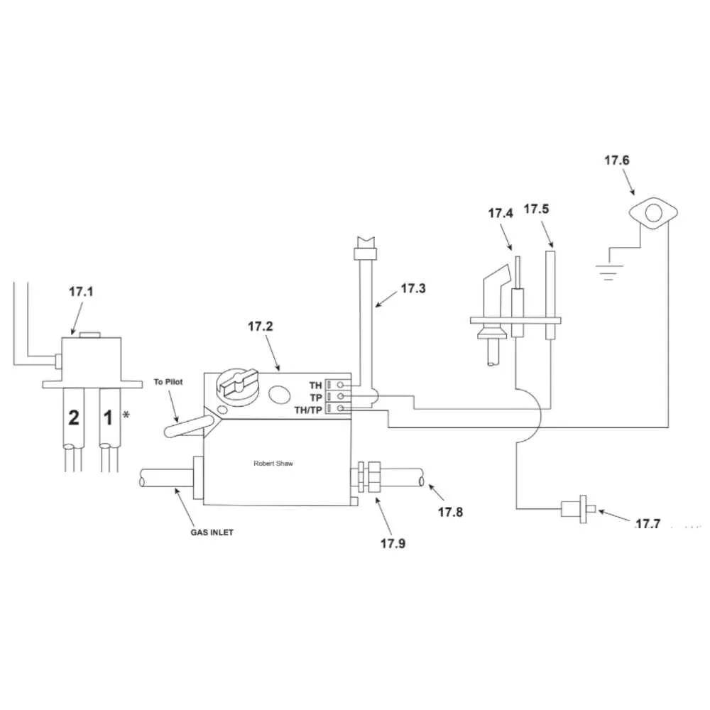
Connect the red wire from the thermostat to terminal TH, and the white or common line to terminal TH/TR. The TR terminal links to the transformer’s neutral side. Always match wire colors and labels according to the specific unit’s instruction plate, as mismatching can cause ignition failure or valve lockout.
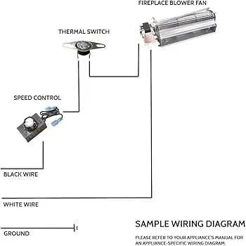
Verify that the limit switch interrupts the circuit between the transformer and control valve during an overheat condition. Test continuity before and after installation. Some modern setups integrate a remote receiver or wall switch; connect these in series with the thermostat input if supported.
Before powering the system, double-check that all spade terminals are firmly seated and that no exposed conductors can short against the chassis. Use only copper conductors rated for 60°C or higher. Route cables away from hot surfaces and secure them with non-conductive clamps.
Electrical Layout and Connection Guide
Always disconnect power before modifying any circuits. Begin by identifying the main control unit, typically located behind the front panel or beneath the burner assembly. Locate the 24V transformer, which supplies low-voltage current to the ignition control and remote receiver.
Connect the thermostat wires to terminals labeled TH and TH-TR. Ensure polarity is consistent if digital controls are used. For millivolt systems, route the two-strand wire from the wall control to the terminal block on the valve without crossing or grounding.
Attach the ignition module’s leads directly to the pilot assembly: white wire to the spark electrode, and black to the flame sensor. For safety switches like the thermopile or spill switch, insert them inline between the valve and the power source, using spade connectors for secure contact.
Verify grounding on all metal chassis connections using the green wire to avoid interference. Use wire nuts and UL-listed connectors to join segments, and secure them away from heat sources using insulated clips or brackets.
Final check: test continuity with a multimeter across each contact point before reapplying power. If the unit includes a remote module, ensure its receiver connects to the valve via a dedicated lead, not through the thermostat loop.
How to Connect the Thermostat to a Flame Control Board
Start by identifying the TH and TH/TP terminals on the main ignition module. These contacts are typically located on the low-voltage section of the control panel and are marked clearly.
Ensure the thermostat is a millivolt-compatible model. Low-voltage electronic units (24V) are not suitable unless the regulator supports dual voltage inputs.
Run a two-conductor wire (18 AWG recommended) from the thermostat location to the controller housing. Strip insulation from both ends by 1/4 inch to ensure solid contact.
Attach one conductor to the TH terminal and the other to the TH/TP terminal. Polarity does not matter in a millivolt system, but secure screw terminals tightly to avoid intermittent operation.
Test continuity at the thermostat. When calling for heat, the circuit between TH and TH/TP should close. Use a multimeter to verify the signal reaches the internal relay coil.
If using a programmable unit, disable any voltage output settings. Set it to “millivolt mode” or “dry contact” to prevent circuit board damage.
Finally, restore power or open the pilot valve to test functionality. The pilot flame should engage once the thermostat calls for heat and remain active until satisfied temperature is reached.
Wiring Instructions for Wall Switch Integration with Millivolt Systems

Connect the wall-mounted control directly to the TH and TH/TP terminals on the valve assembly. No external power source is required, as millivolt setups generate their own voltage via the thermopile.
- Ensure the unit is in the OFF position before handling terminals.
- Use 18 AWG or thicker stranded copper conductors rated for low-voltage control.
- Run a two-conductor cable from the switch location to the valve compartment.
- Strip approximately 3/8 inch of insulation from both ends of each wire.
- Connect one lead to the TH terminal, and the second to the TH/TP terminal using ring or spade connectors for secure fit.
- Secure all connections to avoid accidental disconnection due to vibration or thermal expansion.
- Test continuity between the two conductors with the switch in both ON and OFF positions to confirm correct operation.
A properly installed control will complete the circuit when toggled ON, allowing the thermopile-generated voltage to activate the valve solenoid.
Power Supply and Ignition Module Connections in Direct Vent Units

Ensure the main power source delivers a stable 120V AC line with proper grounding to avoid electrical faults. The ignition control board must be connected to a dedicated circuit breaker rated at 15 amps to prevent overloads during startup sequences.
Connect the low-voltage transformer secondary output (typically 24V AC) directly to the ignition module’s power terminals, observing polarity where specified by the manufacturer. Use wire gauge no smaller than 18 AWG to minimize voltage drop and maintain reliable spark generation.
For ignition module interfaces, link the safety valve solenoid and flame sensor leads according to the control unit’s color-coded terminals. Confirm all terminal screws are tightly secured to avoid intermittent connections that could disrupt ignition cycles.
Route control cables separately from high-voltage lines to reduce electromagnetic interference affecting sensor signals. Utilize wire clamps and protective conduits to secure all leads along their paths, preventing mechanical strain or abrasion during operation.
Before finalizing connections, verify continuity and insulation resistance with a multimeter. Perform a functional test of the ignition sequence to confirm correct spark timing and flame establishment. If any irregularities occur, inspect the transformer output voltage and module input signals promptly.