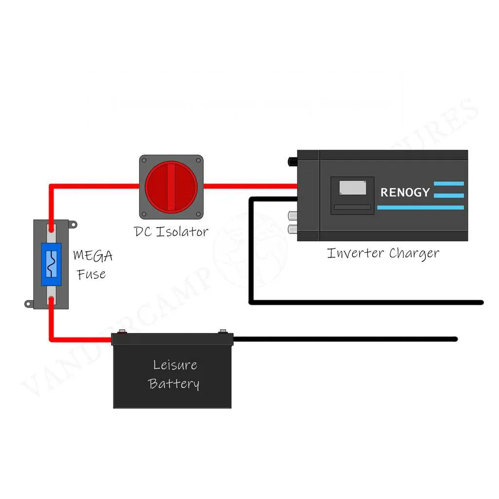
Start by connecting the power source to the DC input terminals on the conversion unit. Ensure the cables are sized appropriately to handle the maximum current load. For most recreational vehicles, a 10 AWG wire is suitable, but always verify against your specific system’s requirements. Secure the connections tightly to avoid any loose terminals that may result in overheating.
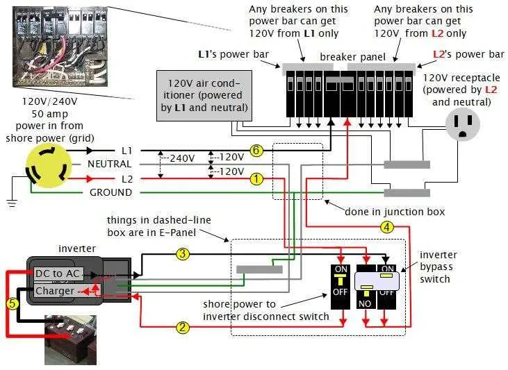
Next, link the output leads to the distribution panel, keeping the polarity consistent. This step is crucial to maintain system integrity. Use high-quality copper wire with insulation rated for outdoor use to prevent deterioration over time. Remember that proper grounding is essential to avoid potential shocks or short circuits. Attach the ground wire to a suitable metal frame or chassis of the RV to complete the circuit safely.
Incorporate a fuse or breaker between the main unit and the power grid to prevent overloading the system in case of a fault. Opt for a fuse rated at 15% higher than your expected load to allow safe operation without unnecessary interruptions. Check the capacity of your unit and select the appropriate fuse size accordingly.
Finally, verify the integrity of all connections with a multimeter, ensuring there are no voltage drops or short circuits. Regular maintenance and inspections of the electrical setup will prolong the life of your equipment and enhance safety on the road.
RV Power Setup Guide
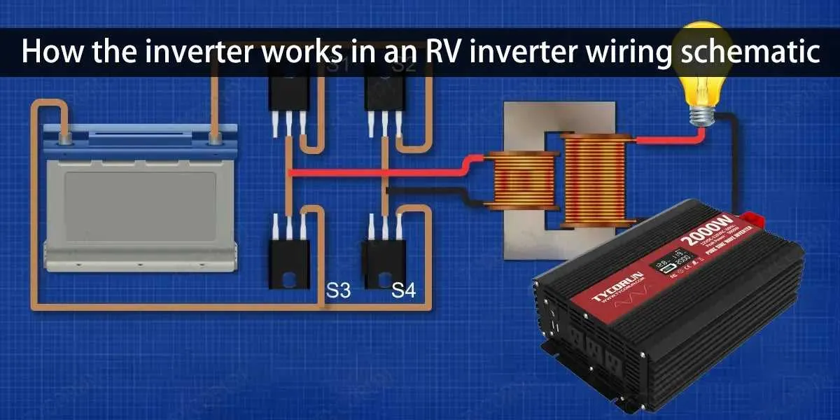
To ensure efficient power conversion in your RV, follow these detailed steps when connecting your energy converter. A proper configuration will prevent overloading and optimize performance.
- Start by choosing a suitable DC to AC power converter, considering your appliances’ power demands.
- Use cables that are rated for the maximum current draw. For typical RV applications, 6 AWG cables are a solid choice for connections to the battery bank.
- Make sure the battery bank voltage matches the input requirements of the system. Most RV setups use 12V or 24V systems, so match accordingly.
For battery connections, use heavy-duty lugs to minimize voltage drop, and ensure they are properly tightened to prevent any loose connections.
- Connect the positive terminal of your battery bank to the input of your energy converter, using the appropriate fuse or breaker for safety.
- Attach the negative terminal to the converter’s negative input, ensuring all connections are secure and corrosion-free.
- If using an external surge protector, wire it between the converter and the RV’s power panel for additional protection.
Always double-check polarity, as reversing connections could cause significant damage to your system.
How to Connect an Inverter to an RV Battery System
Start by ensuring the battery voltage matches the unit’s requirements. Typically, RV batteries operate at 12V, while most devices require 110V or 220V AC power. Choose the right power converter based on the load you’ll be running.
Step 1: Disconnect the RV battery before beginning. This will prevent short circuits or accidental shocks during installation.
Step 2: Identify the positive and negative terminals of your power source. Connect the positive lead from the unit directly to the battery’s positive terminal, using a high-quality copper wire of appropriate gauge for the current draw. Use a fuse between the battery and the system for protection.
Step 3: Attach the negative terminal lead to the battery’s negative terminal. Ensure the connection is firm and secure. Poor contacts can lead to heating or failure.
Step 4: After securing the battery leads, connect the output terminals of the power converter to your RV’s AC system. If your RV system uses a breaker box, make sure you wire the output through a dedicated breaker for safety.
Step 5: Once the connections are complete, test the system. Turn the power on and check voltage readings to confirm proper operation before using any devices.
Tip: Use the shortest and thickest cables possible for both the positive and negative connections to minimize resistance. Also, invest in a battery monitoring system to track voltage levels and avoid overcharging or deep discharges, which can damage the battery.
Understanding the Wiring Components of an RV Inverter System
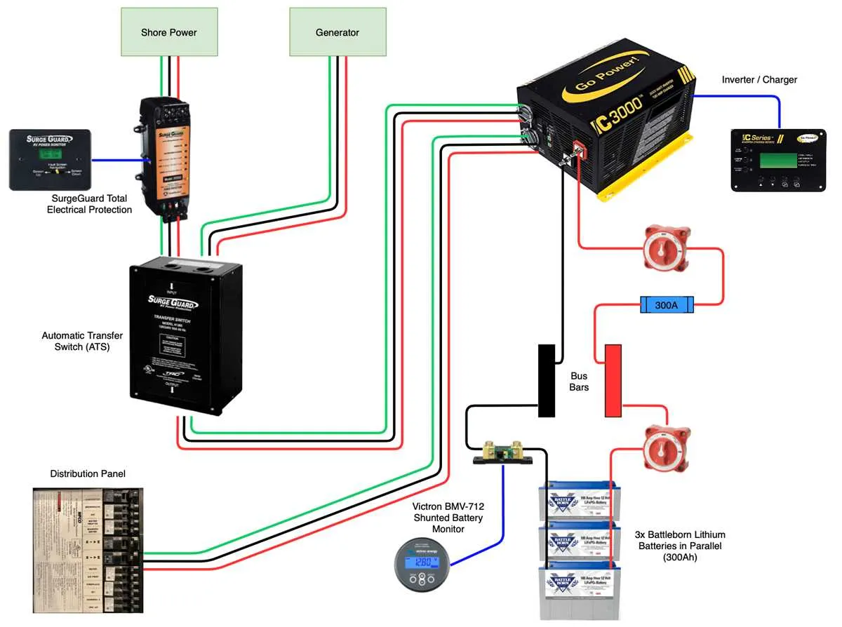
Ensure proper power conversion by using high-quality cables and connectors when setting up the electrical components of your RV’s power system. Use copper cables for optimal conductivity, and always match wire gauge with current requirements. For example, a 4 AWG wire is ideal for high-power applications up to 4000 watts, while a 6 AWG is sufficient for smaller units.
Install a dedicated fuse or circuit breaker on both the DC and AC sides of the unit to prevent damage from short circuits or overloads. A 150-amp fuse on the DC side ensures protection for high-current flow, while a 30-amp breaker on the AC side safeguards against overloading during operation.
Grounding the system correctly is essential for safety. Connect a reliable ground wire from the device to the RV’s chassis to prevent electrical hazards. The ground wire should be at least 10 AWG to handle any fault current that may arise.
Proper battery connection is key to maintaining a stable power flow. Use solid, corrosion-resistant terminals and ensure tight connections to avoid any power loss. Be sure to use a battery isolator to manage the charging and discharging process, preventing damage to both the battery bank and the power source.
Consider the power input and output configurations. Make sure to use appropriate connectors for AC outlets and DC terminals to avoid wear over time. Opt for connectors rated for at least 20 amps to handle typical RV loads safely.
Monitor the system’s health with a digital display unit that can provide real-time information on voltage, current, and system status. Regularly check connections to ensure everything remains secure and free from corrosion.
Common Mistakes to Avoid When Connecting an RV Power System
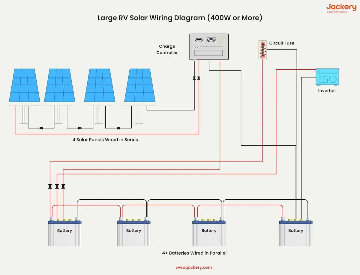
Incorrectly sizing the cables is one of the most frequent errors. Always choose cables that match the current requirements of your system. Underestimating the necessary wire gauge can lead to overheating, voltage drops, and even fires. Make sure to consult a wire size chart based on amperage and length of the run.
Another common pitfall is poor grounding. Failing to establish a solid ground connection can cause electrical issues, including system malfunctions and safety hazards. Ensure the ground wire is securely connected to a clean, rust-free surface on your RV frame.
Not installing proper fuses or circuit breakers is another mistake. These components protect your setup from overcurrent and potential damage. Ensure that fuses are appropriately rated for the equipment’s capacity, and install breakers near the power source to safeguard your system from short circuits.
Many individuals also neglect the proper placement of components. Avoid placing sensitive electronics too close to heat sources or areas exposed to excessive moisture. Install components in cool, dry locations to prevent heat buildup or corrosion, which can degrade performance over time.
Improper ventilation can also affect your system’s performance. Ensure there is adequate airflow around the equipment to prevent overheating. Using an enclosed space without ventilation can reduce efficiency and cause damage.
Finally, skipping system testing before full use can lead to undetected faults. After all connections are made, thoroughly check the system for any signs of malfunction, unusual heat, or unexpected behavior. Regular testing ensures reliability and longevity.