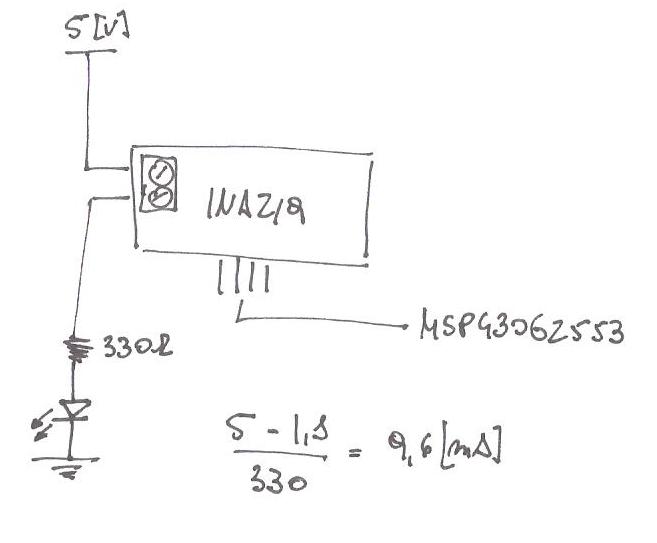
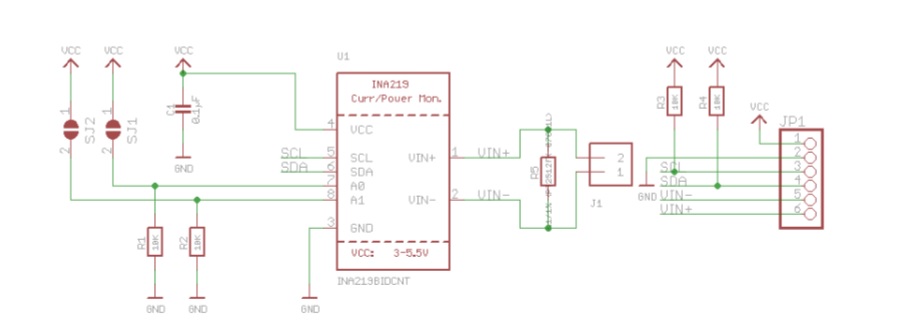
Take a look at the schematic, and you will notice that the breakout board consists of a shunt resistor (RS), the INA chip, and an output resistor (RL).
While RS. Wiring. by lady ada.
The INA breakout board can be powered by the 5v pin on your Arduino and communicates via I2C. Wiring. by lady ada. The INA breakout board can be powered by the 5v pin on your Arduino and communicates via I2C.
Looking at the circuit diagram at the bottom of Texas Instruments site and for the 3. schematron.org Python Installation of INA Library Schematic & Fabrication Print Wiring.
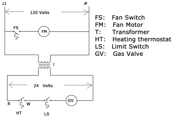
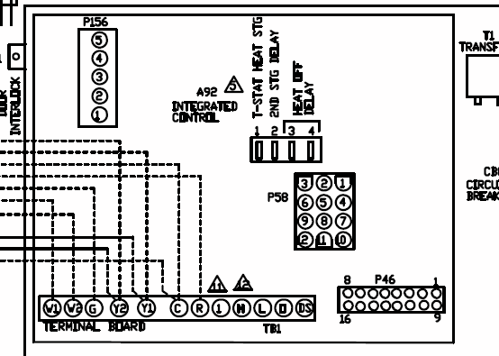
The INA breakout board can be powered by the 5v pin on.A wiring diagram is a simple visual representation of the physical connections and physical layout of an electrical system or circuit. It shows how the electrical wires are interconnected and can also show where fixtures and components may be connected to the system.
Wiring the i2C INA ZERO Drift, Bidirectional Current/Power Monitor with MCU This is the INAB breakout module to measure both high side voltage and DC .
This guide was first published on Oct 26, It was last updated on Nov 27, This page (Downloads) was last updated on Aug 10, Mar 30, · Looking at the circuit diagram at the bottom of Texas Instruments site and for the example in the learn adafruit guide site listed below i was thinking: To measure solar panel voltage and current: INA Vin+ to + of solar panel INA Vin- to battery + Battery – to arduino GND Solar panel – to arduino GND Is this or anything wright? The INA breakout board can be powered by the 5v pin on your Arduino and communicates via I2C.Arduino INA Current Voltage Tutorial | Henry’s BenchINA Current/Power Monitor with Electron – Library and Wiring Help – Libraries – Particle
