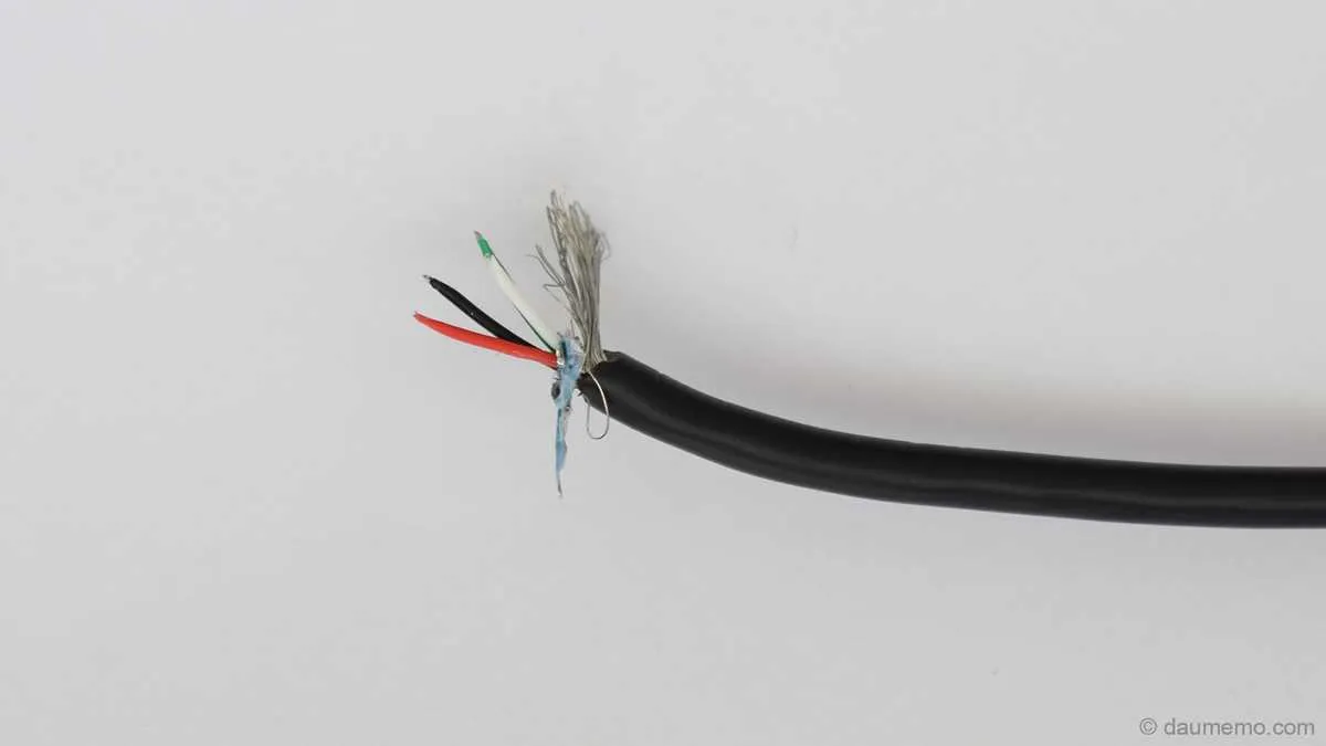
If your data transfer line lacks the typical dark conductor for grounding, start by confirming the function of each strand using a multimeter. Focus on locating the positive power feed, the data positive, and data negative lines, which often follow color codes such as red, white, and green.
Verify continuity between the device and the connector pins before powering on. Absence of a dedicated earth line means relying on proper shielding and correct pairing of the signal carriers to avoid interference or data loss.
For assemblies missing the common return path, ensure your setup grounds through the housing or the connector shell to maintain signal integrity. If shielding is compromised, consider adding an external grounding solution or replacing the assembly with one conforming to recognized standards.
Wiring Diagram USB Cable No Black Wire

When a data connector lacks the typical ground conductor, identify the shielding or metal casing as the return path. In some cords, the absence of the standard dark conductor indicates that the ground is integrated into the shield foil or braided mesh. Test continuity between the connector shell and the common return terminal to confirm this configuration.
For power and signal lines, note that the usual red line carries +5V and the white and green conductors handle data transfer. Without the common ground conductor, the shield or chassis ground must be connected to the device’s grounding point to maintain signal integrity and safety.
Always verify pinouts with a multimeter before making connections. If the usual negative lead is missing, do not assume data or power leads can substitute; instead, rely on the external shield connection as the common reference. This ensures proper functionality and prevents damage.
Identifying Conductors Without a Ground Lead
When a common grounding strand is missing, locate the reference line by following these steps:
- Check for a metallic shield or foil inside the sheath–this often serves as the ground return path.
- Measure continuity between the outer connector shell and each conductor to find the grounding equivalent.
- Identify the power supply line, typically red or marked with a positive sign, as the voltage source.
- Locate data transmission pairs–usually twisted and color-coded green and white or similar tones.
- Use a multimeter to test voltage between conductors, confirming which serve as data minus and data plus.
If color coding deviates from standards, trace the connections back to the device interface for verification. In some variants, the ground function may be integrated with the shield or omitted if the device uses alternative grounding methods.
- Always isolate conductors before testing to avoid short circuits.
- Document conductor colors and positions to prevent confusion during assembly.
- Utilize pinout references from manufacturer datasheets when available.
How to Test Connections When Ground Line Is Absent
Start by identifying the red (power), white (data-), and green (data+) leads. Use a multimeter set to continuity mode. Confirm the path from each end by probing the terminals:
| Lead Color | Typical Function | Expected Pin (Type-A plug) | Multimeter Test Result |
|---|---|---|---|
| Red | +5V Supply | Pin 1 | Beep or ~0Ω when probed to opposite +5V contact |
| White | Data Minus | Pin 2 | Beep or ~0Ω to corresponding data- line |
| Green | Data Plus | Pin 3 | Beep or ~0Ω to corresponding data+ line |
If the return conductor is absent, verify voltage stability across red and outer shell using DC mode. Expected output is close to +5V. A reading of 0V indicates missing return continuity. Avoid connecting such configuration to power sources without confirming functional grounding via an external probe or alternate chassis contact.
Alternatives to Black Wire for Ground in USB Cable Wiring
Use a white or bare conductor to handle ground functionality when the standard dark-colored lead is missing. In legacy configurations, the unshielded strand often serves as the return path for current, particularly when insulation is omitted for grounding purposes.
Green or blue lines are not suitable substitutes for return paths, as they are typically designated for data transmission. If a shield braid is present, it can be soldered directly to the host’s ground plane, effectively replicating the missing return line’s role.
For modified or DIY assemblies, designate the unused outer braid or foil wrap as the negative rail. Secure this element with proper strain relief and ensure electrical continuity with the device’s ground point.
Always verify continuity between the substitute lead and the ground pin on the host connector using a multimeter. Resistance should be near zero to ensure safe operation and signal integrity.