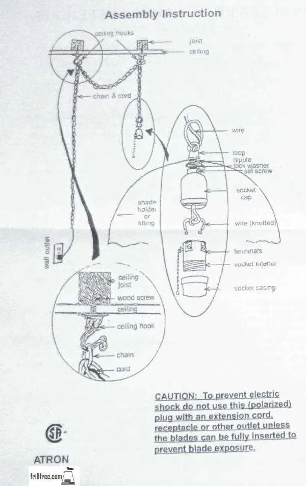
To ensure reliable operation of your earthworm-powered fishing device, follow a clear connection scheme with exact color codes and component placements. Use a 12V power source connected directly to the switch terminals, avoiding intermediate splices that can cause voltage drops. Employ insulated, weather-resistant cables rated for outdoor use to maintain safety and performance under wet conditions.
Key components: a waterproof toggle or push-button controller, high-capacity battery, and a well-labeled terminal block to organize circuit paths. Make sure the current flow matches the motor specifications to prevent overheating or premature failure. A fuse rated slightly above the motor’s max draw is essential for overload protection.
Attention to polarity is critical: red wires should connect to the positive battery terminal and black to negative or ground points. Confirm all joints with a multimeter before powering up to avoid short circuits. Clear identification of each cable’s role in the assembly reduces troubleshooting time and ensures swift repairs in the field.
Wiring Configuration for the Shock Device
Connect the positive lead directly to the power source’s 12V terminal, ensuring a secure and corrosion-free contact point. The negative cable must be grounded to a clean metal surface on the frame for optimal conductivity. Use insulated, weather-resistant cables rated for at least 10 amps to prevent voltage drops and potential shorts.
Incorporate an inline fuse of 15 amps close to the power supply to protect the circuit from overloads. Employ quick-disconnect terminals for ease of maintenance and troubleshooting. Verify that all connectors are crimped properly and sealed with dielectric grease to resist moisture ingress.
Route the cables avoiding sharp edges and moving parts; secure them with non-conductive zip ties at regular intervals to minimize vibration damage. Test the entire circuit with a multimeter before operation to confirm continuous electrical flow and correct polarity.
Identifying Key Components in Worm Shocker Wiring

Focus first on locating the power source terminals, usually marked as positive (+) and negative (−), which supply the main voltage for operation.
- Battery Connector: Thick gauge leads designed for secure attachment to a 12V or 24V battery.
- Control Module: The central electronic unit regulating pulse delivery; often encased in a weatherproof housing.
- Trigger Switch: A push-button or toggle switch wired inline to activate the circuit on demand.
- Output Electrodes: Metal prongs or rods that deliver the electric pulses; ensure they are corrosion-free and firmly connected.
- Ground Wire: A dedicated return path typically connected to a metal rod driven into the soil for circuit completion.
Trace all connections for solid crimps or solder joints to avoid voltage drops. Identify any inline fuses or circuit breakers placed near the battery terminal to protect against short circuits.
- Locate the power input leads and confirm correct polarity.
- Follow the cables from the control unit to the activation switch ensuring continuity.
- Verify the electrode leads for insulation integrity and secure mounting.
- Check grounding for minimal resistance to ensure effective current flow.
Prioritize testing each segment with a multimeter set to voltage and resistance modes to confirm the integrity and correct operation of every element within the system.
Step-by-Step Connection Process for Worm Shocker Setup

Begin by securely attaching the power lead to a 12V DC source with a proper fuse rated at 10A to prevent electrical overload. Connect the positive cable from the control unit directly to the battery’s positive terminal, ensuring a tight and corrosion-free link. Attach the ground wire firmly to the vehicle chassis or battery negative terminal for stable circuit performance.
Next, link the output cable from the control module to the stimulation pad terminals, verifying polarity is correct–positive to positive, negative to negative–to guarantee effective current flow. Use insulated connectors or crimp terminals to maintain secure and vibration-resistant contacts.
Install an inline switch between the power source and the main unit to enable quick activation and deactivation. Confirm all connections are tight and free from exposed wires to avoid short circuits or electrical faults during operation.
After assembly, test the system by activating the control switch briefly while monitoring for consistent pulse delivery through the output pads. Adjust connections if there is any fluctuation or weak response. Finally, secure all cables with zip ties or clamps to prevent movement and damage under normal use conditions.
Troubleshooting Common Electrical Connection Issues in Worm Shockers
Start by verifying all connectors for secure attachment and absence of corrosion, which often causes intermittent power loss. Use a multimeter to measure voltage at each junction point; a drop below 12V typically signals a faulty contact or broken lead.
Inspect insulation integrity along cables to identify cracks or abrasions that may cause short circuits or grounding faults. Replace damaged sections with high-quality, weather-resistant replacements to maintain circuit reliability.
Check the relay and fuse components specific to the device’s power supply line. A blown fuse or malfunctioning relay often results in complete system failure. Replace with manufacturer-recommended parts to ensure compatibility.
Confirm polarity orientation on all terminal blocks; reversed connections can prevent activation or damage internal electronics. Mark cables during maintenance to avoid future miswiring.
Examine the main control unit for signs of overheating or moisture intrusion, as these can disrupt signal flow. Use dielectric grease on connectors to prevent oxidation in humid environments.
Test the trigger mechanism wiring separately to isolate faults. Continuity failures here typically manifest as non-responsiveness despite proper power supply. Repair or replace the trigger cable as needed.
Regularly clean all contact points with contact cleaner to remove dirt and oxidation layers that impede electrical flow. Avoid abrasive tools that might damage connector surfaces.