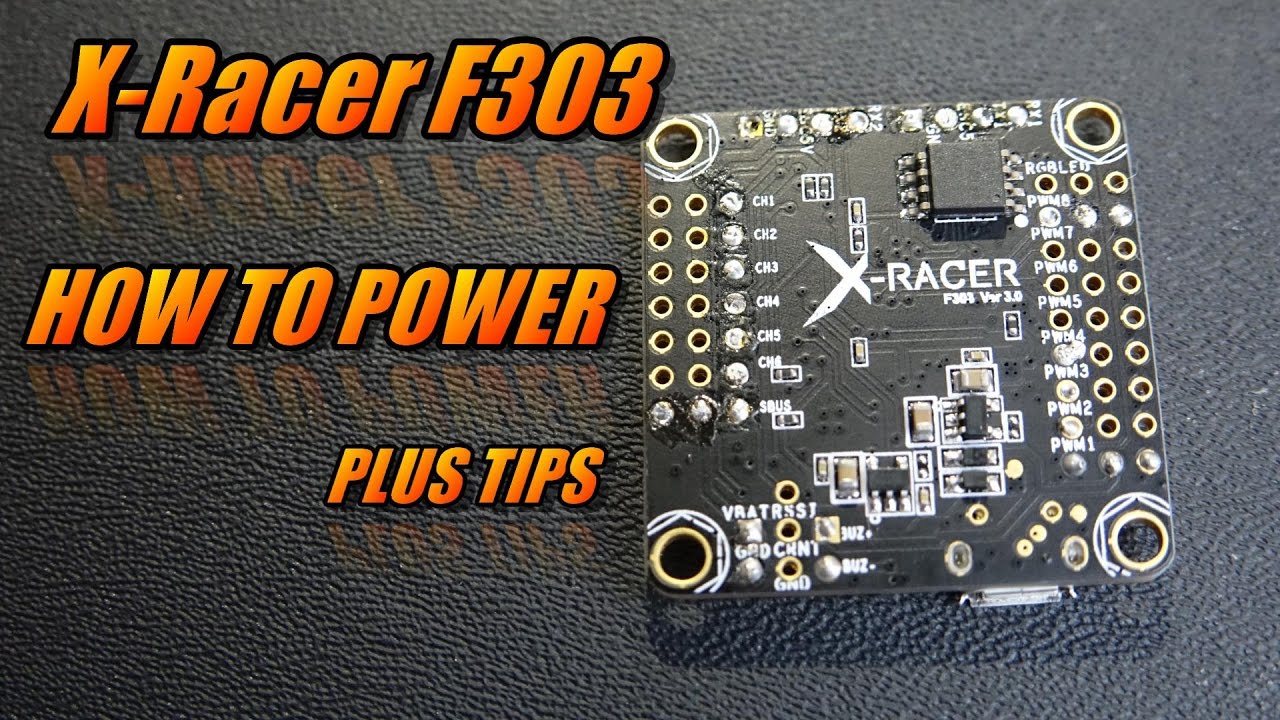
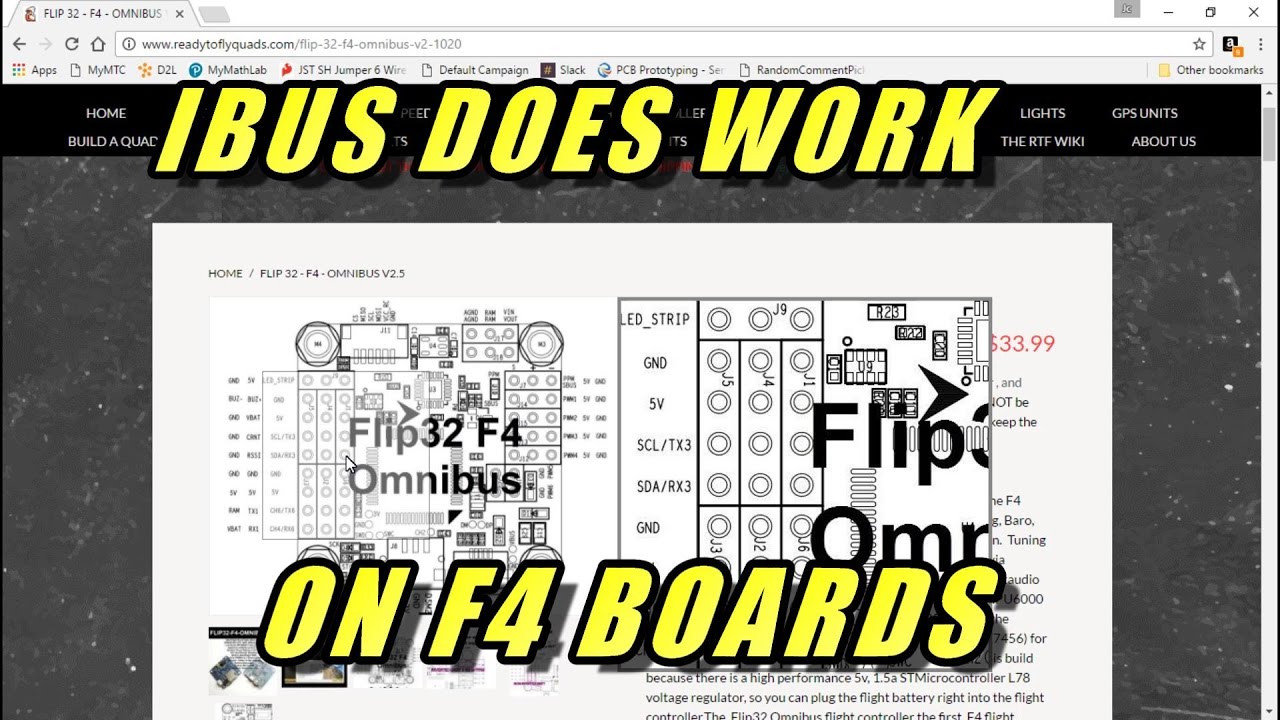
LiPo Input: S (5VV); Power rail: v,5v,9v,vbat; A (MAX display) pads along with camera power signal pads; Dedicated VTX connection Support RX: Dedicated Sbus hardware inverted,Satellite RX, Ibus,TBS 1) 10/ 10 for solder pad layout. X Racer V F3 Flight Controller (Out of Stock). I am using the RROSD Pro V2 PDB, X-Racer F V Flight from the receiver plugged into the flight controllers PWM RC inputs(Channel ).
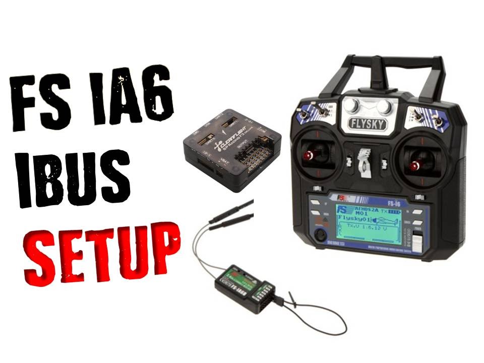
How to Connect FS-X6B to Wizard X220 via i-BUS – Help for Beginners
. voltage over iBus so you can possibly clean up the wiring by having one.
The X-Racer F flight controller was designed for the serious racer. X-Racer X-1 F3 Flight Controller V2 with Frsky Rx and OSD Integrated specifically for Sbus, which is our recommended connection for flight control.
Make certain all channel inputs match corresponding outputs or else schematron.org Seriously Pro. Seriously Pro Racing F3 Flight Controller Manual (Revision 4) Stackable design – perfect for integrating with OSDs and power distribution boards.
• 16 PWM I/O Do not connect any input or output to any other input or output unless specifically stated. ..
Choose model/mixer (default is Quad X). • Enable.
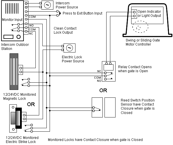
FS-iA6B – If you are flying racing miniquads, this is the receiver you’ll want for now. For the same reason, though, you should not wire your IBUS receiver to a To bind your FS-i6 to it, power the TX up while holding the bind button. on the throttle to get that value or consult your FlySky radio’s manual.Cc3d wiring diagrams furthermore peugeot 7 power steering pump wiring diagram as well as nearapp moreover mazda 3 central locking wiring diagram further tarot mini wiring diagram moreover honda hurricane wiring diagram furthermore rc plane wiring diagram along with rc boat wiring diagram together with bluejay f4 wiring diagram.
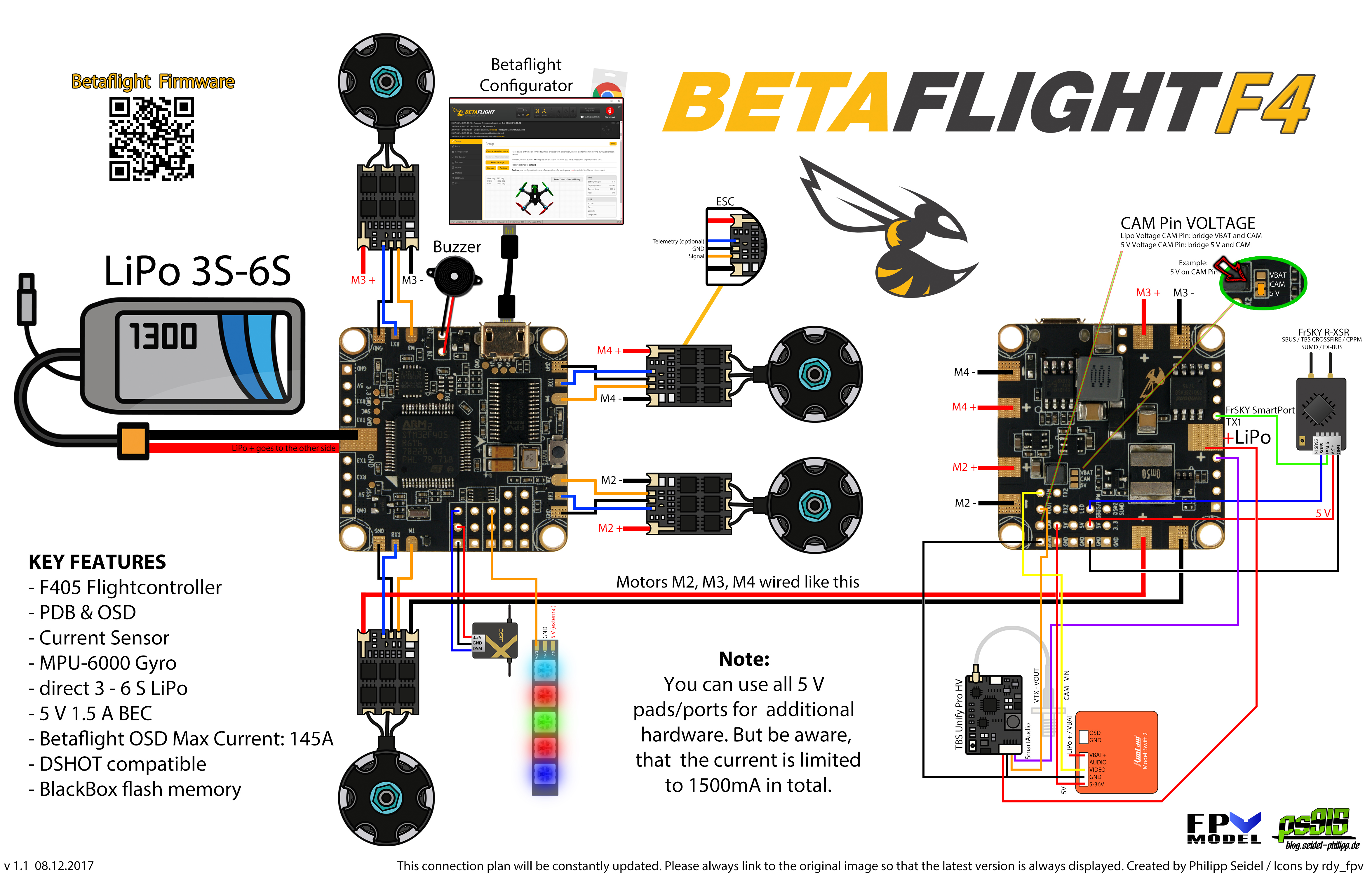
In our wiring diagram, you can see that the Smart port of XSR receiver wired to TX3, and the VTX wired to TX1.
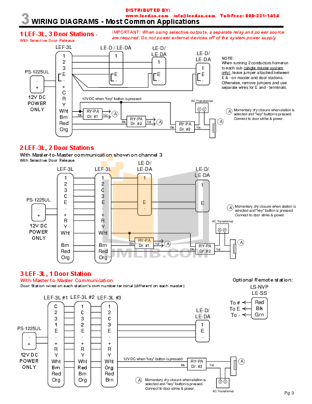
However, if you are using Tramp HV Vtx, the wiring is different. The VTX needs to wire to TX3, and the Smart port wired to TX1. Combining Flight Controller, OSD, PDB (w/ both 5V and 12V UBEC), Current Sensor and VTX.
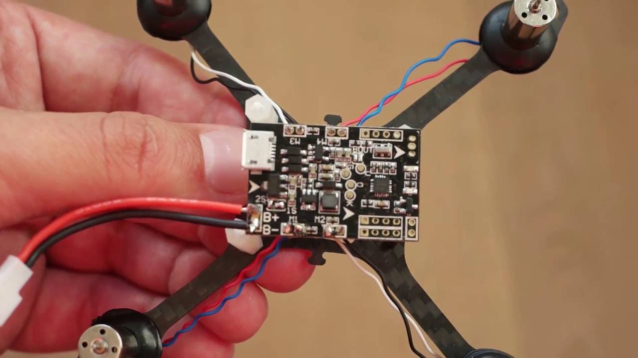
together, this is the board we want!. Base on the SP Racing F3 design, HGLRC re-assigned the wiring and combining the OSD module, VTX (adjustable 25 / / mw) Power Distribution Board into one board, no more messy wiring, support up to 6 ESCs, that means it works for both Quadcopter and Hexactoper.
F4 Advanced Flight Controller – (MPU, STM32F) More Views This Advanced Flight Controller features a powerful F4 processor and is RaceFlight, BetaFlight /5(17). The Seriously Pro Racing F3 Flight Controller (SPRacingF3) was designed to give awesome flight performance • POWER OFF before unplugging, plugging in or making any connections. • Do not connect any input or output to any other input or output unless specifically stated.

• The v supply is for low-current use only. mA MAX.Help With FlySky FS-X6B Receiver : MulticopterCc3d Atom Wiring Diagram | Wiring Library
