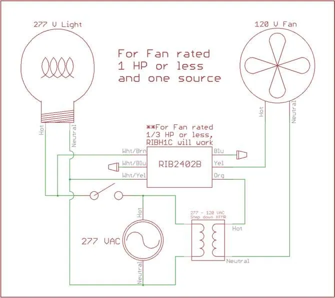
Ensure your system is set up correctly by following these essential steps. First, identify the components involved: a low voltage control unit and a high voltage switching mechanism. These elements will work together to manage the flow of electricity effectively.
Next, connect the terminals to establish a clear path for current. The control unit’s terminals will be used to activate the switching device, which, once triggered, will complete the circuit on the high voltage side. Make sure the load is properly connected to the high-voltage contacts to avoid malfunction.
Use a diagram of the switching mechanism to identify key connections. Pay special attention to the polarity of the input and output terminals. Incorrect connections can result in equipment failure or safety hazards. For added safety, always verify that the high-voltage wiring is isolated from the control circuit.
Once everything is in place, double-check that the activation of the low voltage unit leads to the correct response on the high voltage side. Testing each connection before powering up can help you avoid unnecessary repairs down the line.
Follow these steps carefully to ensure the system functions as intended without issues.
Wiring Instructions for a 120V Switch Setup

To safely connect a 120V control circuit, start by ensuring the correct components are used. Use a control switch rated for 120V AC and verify the current requirements of your load. The first terminal of the switch connects to the live wire (black), while the second terminal should go to the load (such as a motor or light). A grounding connection must also be established between the control and the circuit panel for safety.
Next, the neutral wire (white) from the panel must be connected directly to the load. For proper operation, the common terminal on the control should be linked to the incoming live wire. Make sure the switch is securely fastened and that all connections are tight to prevent arcing or overheating.
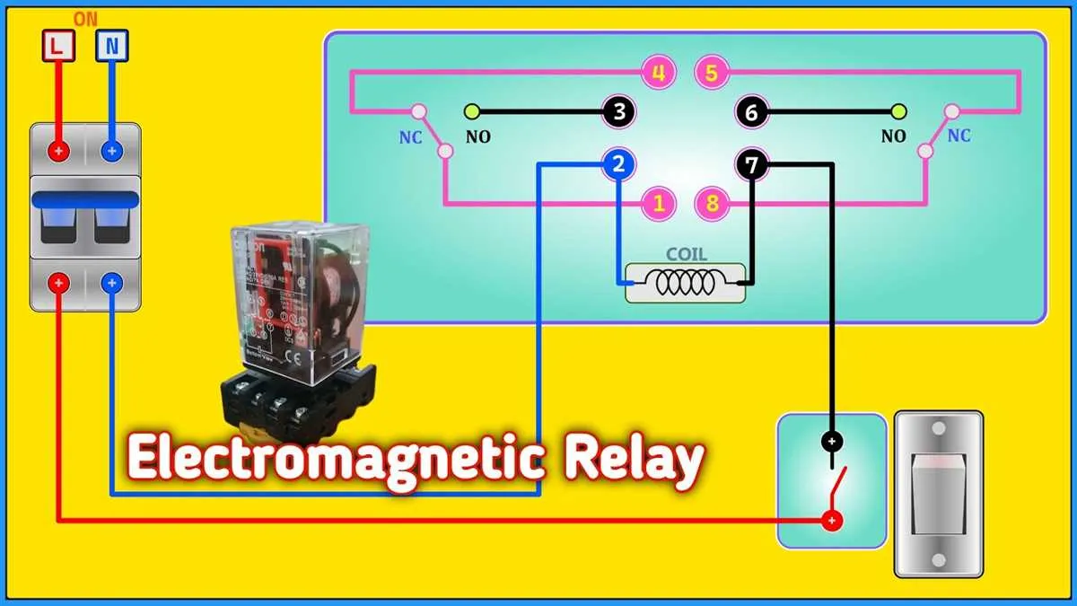
When configuring the control mechanism, pay attention to the orientation of the terminals. The normally open (NO) contact should be positioned to connect with the control mechanism when activated, allowing current to flow when needed. The normally closed (NC) contact will stay engaged unless the system is powered on.
After completing the connections, conduct a final test to ensure the system activates correctly without any issues such as short circuits or loose wires. Always use a multimeter to check the voltage at different points to confirm proper function.
How to Connect a Basic 120V SPDT Switch for Home Appliances
To properly set up a single-pole, double-throw (SPDT) switch for controlling a home appliance, follow these steps:
1. First, identify the common terminal (COM), normally open (NO), and normally closed (NC) contacts. These will be crucial in making the correct connections.
2. Connect the common terminal (COM) to the live wire from the power source. This ensures the current flows when the switch is activated.
3. Attach the normally open terminal (NO) to the appliance’s live input. This is the contact that will complete the circuit when the switch is engaged, powering your appliance.
4. For appliances that should be powered off when the switch is on, connect the normally closed terminal (NC) to the appliance’s live input. When the switch is off, the current will flow through this terminal instead.
5. Secure the neutral wire directly to the appliance, bypassing the switch. Neutral wiring does not need to pass through the control mechanism as it only completes the circuit when connected with the live wire.
6. Ensure the ground wire from the power source is properly connected to the appliance to avoid any electrical hazards.
7. After making these connections, check all terminals for tightness and double-check that no loose wires are exposed to prevent any shorts or damage.
8. Once all connections are secure, test the setup by flipping the switch on and off, verifying the appliance’s response accordingly.
Motor Control in HVAC Systems: Connection Guide
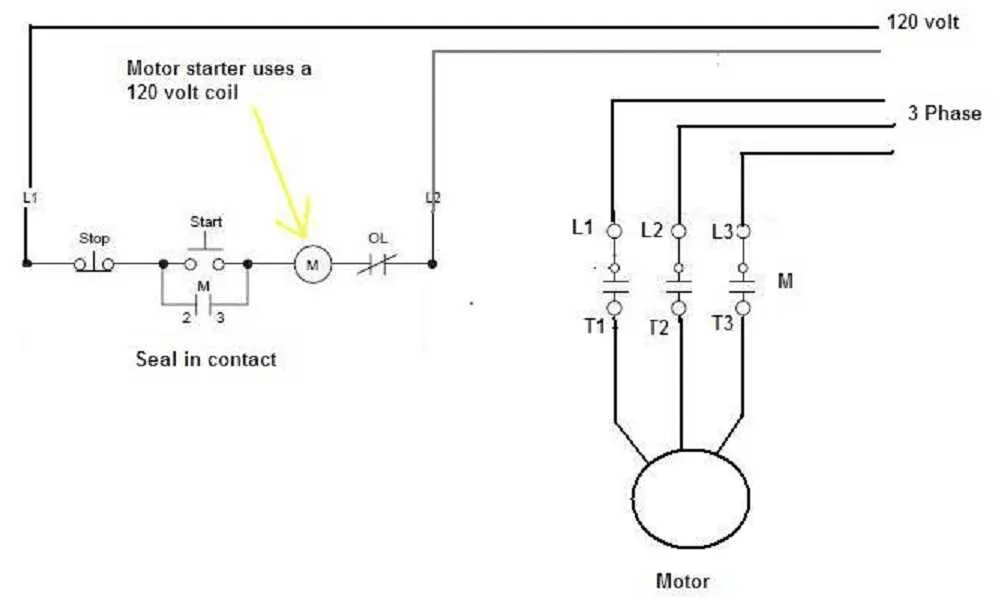
For controlling motors in HVAC systems, utilize a switching mechanism to handle 120V AC power. Start by connecting the coil terminals to the control circuit, ensuring a reliable low-voltage input. The common terminal should be linked to the power source, while the normally open contact will connect to the motor’s power input. This setup allows the motor to be activated when the control signal energizes the coil, closing the circuit and powering the motor.
Ensure the use of components rated for at least the motor’s current capacity. The switch should be able to handle inrush current without damage. It’s critical to incorporate proper fusing on the power side to safeguard the circuit. Use thick gauge wire for power connections to minimize resistance and heat buildup.
For safety and reliability, mount the components in a secure, well-ventilated area away from moisture or excessive heat. Double-check all connections to prevent shorts, and use locking terminals or crimp connectors for secure and long-lasting contact. If integrating this setup with a thermostat or a controller, verify compatibility with the activation signal to ensure the system operates as expected.
Common Mistakes to Avoid When Connecting a 120V Control Circuit

Improperly connecting components can cause malfunctions or even damage. Here’s what to avoid:
- Ignoring Proper Component Ratings: Always verify the voltage and current ratings of your switch and control devices. Using an underrated component could lead to overheating or failure.
- Incorrectly Identifying Terminals: Misidentifying the load, common, or trigger terminals can prevent the circuit from functioning properly. Ensure you’re connecting the right wires to the correct pins, based on manufacturer guidelines.
- Failing to Use a Ground Connection: A missing or faulty ground can lead to erratic behavior or pose a safety risk. Always ensure the circuit is grounded properly to prevent potential electrical hazards.
- Overloading the Switching Element: Don’t exceed the maximum load that can be handled by the switch. If too much current is passed through, it can cause irreversible damage to the component.
- Not Double-Checking the Polarity: For components that require specific polarity, such as DC control devices, ensure proper orientation of positive and negative leads. Reversing these can prevent activation or even cause short circuits.
- Leaving Wires Exposed: Exposed conductors can lead to shorts and electrical shocks. Always use proper insulation and cover any unused or live terminals to avoid accidental contact.
- Using Low-Quality Wiring: Ensure the wire gauge is suitable for the load. Thin wires can overheat or cause voltage drops, while excessively thick wires can be difficult to manage and increase complexity.
- Overtightening Terminals: Applying excessive torque when securing wires can damage the components or cause stress fractures. Tighten terminals just enough to create a secure connection.
- Neglecting to Check for Loose Connections: Loose connections can lead to intermittent failures. Always inspect the system after installation to ensure all connections are solid and secure.