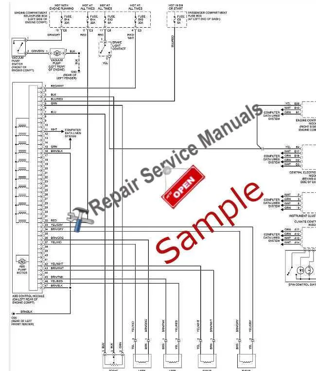
To ensure proper functionality and maintenance of the electronic safety features in classic vehicles, it’s crucial to study the layout and connections involved in the early anti-collision measures. This set of instructions serves as a guide to decoding the specific wiring and components that work together to prevent wheel lock-up under sudden stopping conditions. If you’re working on a vehicle from the early 70s, refer to this diagram to avoid confusion when troubleshooting the safety mechanism.
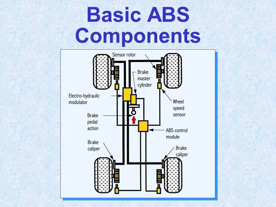
The key to understanding this component lies in identifying the sensors, hydraulic circuits, and the control unit that interacts with them. Start by ensuring all connections between the speed sensors and the controller are intact and free of corrosion. These elements form the heart of the mechanism, helping the vehicle maintain stability when braking force is applied unevenly.
In the event of malfunction, it’s important to check each component in sequence: the sensor wiring, hydraulic modulator, and the control electronics. Misalignment or failure of any of these parts can lead to inconsistent performance, risking unsafe driving conditions. Make sure to verify that the modulator valve functions smoothly and the sensor signal is not interrupted.
Additionally, always ensure that the fluid levels and the entire hydraulic system are in optimal condition. Failure to do so might lead to compromised performance of the entire control mechanism, affecting the safety and reliability of the vehicle.
Cadillac Vehicle Safety Mechanism Overview
To ensure optimal safety and control, it’s crucial to understand the details of the braking enhancement installed in specific vintage Cadillacs. The key component, which helps prevent wheel locking during hard stops, integrates sensors and hydraulic pressure control for smoother deceleration. It operates through a series of interconnected valves, sensors, and a pump, designed to regulate the force applied to each wheel individually.
When inspecting this component in a classic Cadillac, focus on the hydraulic unit located near the master cylinder, as it plays a critical role in modulating pressure. The electronic sensors detect any wheel speed inconsistency, triggering the system to adjust the braking force in real-time, ensuring safe stopping distances under various driving conditions.
Additionally, attention should be given to the wiring connections and sensor alignment. Over time, components may wear, especially rubber seals and hoses, leading to potential leaks or loss of system effectiveness. Regularly check for any fluid inconsistencies or visible corrosion, as this may signal a need for system maintenance or part replacement.
When restoring or maintaining these vehicles, make sure to refer to the original component specifications to ensure compatibility and proper function. If any part is replaced, verify that the new components are correctly calibrated to ensure consistent performance and vehicle safety.
Understanding the Key Components of the 1973 Eldorado Anti-Lock Brake System

The hydraulic control unit, primarily responsible for modulating pressure, is the core component of the vehicle’s emergency response mechanism. It continuously monitors wheel rotation speeds and adjusts fluid flow to prevent wheel lockup during rapid deceleration. The control valve within this unit is highly sensitive to pressure changes, triggering corrective actions when necessary.
A central element in this technology is the sensor network placed at each wheel. These sensors detect the rotational velocity of the wheels, sending real-time data to the controller. Any significant deviation in wheel speed, indicative of potential locking, triggers the response from the hydraulic assembly.
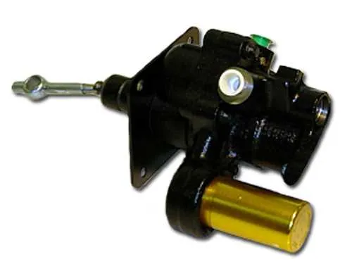
The vacuum booster acts as the assistant to the driver, amplifying force from the foot pedal. This is crucial for ensuring that the corrective measures engage without requiring excessive effort from the driver during critical moments. The integration of this booster with the control unit ensures a seamless operation under high-stress conditions.
The electronic control module interprets data from the sensors, processing it to determine the optimal adjustment of pressure. This module executes the responses based on pre-programmed parameters and dynamic inputs, ensuring that the vehicle’s performance is stable, even in challenging driving conditions.
Lastly, the diagnostic system allows for easy monitoring and troubleshooting. The presence of error codes or malfunctions in the components, such as the sensor failures or issues within the hydraulic components, is crucial for maintenance routines. Regular checks can ensure that the technology remains operational and provides optimal safety performance.
Step-by-Step Guide to Interpreting the Anti-Skid Mechanism Layout

To properly read the layout of the anti-skid mechanism, start by identifying key components such as sensors, control units, and actuators. These elements interact to maintain vehicle stability during braking. Follow these steps to understand the diagram more effectively:
- Locate the sensors: These are often shown as small circles or squares on the layout. Their role is to detect wheel speed and send data to the control unit.
- Find the control unit: Usually depicted as a rectangle, this component processes the data from sensors to adjust the braking force. It is the central element in managing the entire mechanism.
- Examine the actuators: Typically drawn as lines or arrows, actuators are responsible for modulating the brake force based on the control unit’s commands.
- Understand the flow of information: Arrows or lines between components represent data or signal transmission. Follow these connections to determine how information moves through the system.
- Check for warning indicators: Some diagrams will include symbols for error detection. These often appear as triangles or exclamation marks, signaling issues in the components or communication failures.
- Review the electrical connections: Lines indicating power sources, ground connections, and circuit pathways are crucial for interpreting how each part receives its necessary input to function.
Once you are familiar with these elements, practice identifying them on a printed version of the layout. Understanding each part and its function will allow you to troubleshoot, repair, or enhance the system more effectively.
Troubleshooting Common Issues with the Eldorado’s ABS

If the ABS warning light remains on, check the wheel sensors for dirt or damage. Dirty or faulty sensors can cause incorrect readings, triggering the warning. Clean the sensors and inspect wiring for any visible wear or corrosion.
If the brakes feel unresponsive or delayed, the issue may be with the pump or valve. Test the pump’s pressure; a drop in pressure can result from a malfunctioning pump or a blockage in the lines. A faulty pump should be replaced immediately to restore proper functionality.
If you experience erratic pedal behavior, inspect the accumulator for leaks or internal damage. A leaking accumulator can lead to inconsistent pressure, causing pedal pulsation or sponginess. Replace the accumulator if necessary.
Inconsistent stopping power can often be traced to issues with the control module. Verify all connections are secure, and ensure the module is properly grounded. A malfunctioning module will not correctly modulate pressure, leading to poor performance.
If the system fails to activate under heavy braking, inspect the fluid level and quality. Low or contaminated fluid will affect system performance. Drain and replace the fluid if it appears dirty or low.
Finally, if the problem persists despite these checks, it may indicate a deeper mechanical failure. Consult a professional to evaluate the master cylinder, valves, or pressure switch, as these components can wear out over time, leading to total system failure.