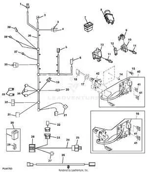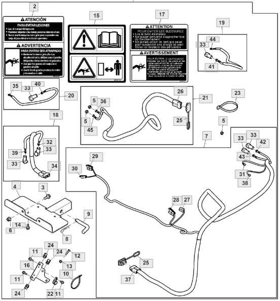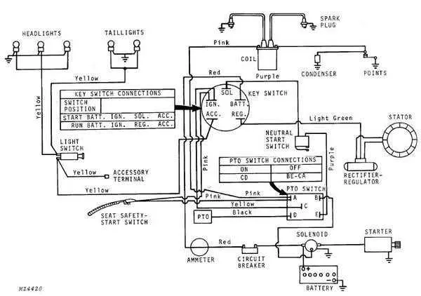
To efficiently troubleshoot or maintain your farming equipment’s electrical system, start by obtaining the specific schematic for your model. This layout illustrates every connection and component, enabling precise identification of circuits and potential faults.
Focus on the color codes and terminal labels within the blueprint, as they are crucial for correctly tracing power flow and signal paths. Misinterpreting these details often leads to prolonged downtime and unnecessary part replacements.
Use a multimeter alongside the schematic to verify continuity and voltage at various points. Systematic cross-referencing of the map with physical wiring ensures accurate diagnostics and safer repairs. Avoid guessing connections without referencing the official layout to prevent damage to sensitive electronics.
Accurate Electrical Schematic for Model A

To ensure proper electrical connections for the Model A tractor, follow this schematic precisely. It maps out all circuits, including ignition, lighting, and charging systems, with clear identification of wire colors and terminal points.
- Locate the battery terminals: Positive connects to the starter solenoid, negative is grounded to the chassis.
- Ignition coil receives power from the switch via a red wire; the black wire leads to the distributor.
- Generator output wire, typically yellow, routes to the voltage regulator and then to the battery.
- Headlight circuit includes a fuse block, with white wires feeding the lamps and a green ground return.
- Safety switches for neutral and brake are integrated via brown and blue leads to the starter circuit.
For troubleshooting, verify continuity with a multimeter along each path indicated. Replace any corroded connectors and ensure all grounds are clean and secure to prevent intermittent faults.
- Use OEM-style connectors and insulation sleeves for durability.
- Refer to serial number-specific revisions as wiring color codes may vary.
- Secure wiring harness with clips to avoid abrasion against metal parts.
Adhering strictly to this electrical layout minimizes breakdowns and optimizes tractor performance under various operating conditions.
Locating and Identifying Key Electrical Components on Model A
Begin by accessing the engine compartment, where the ignition coil is mounted near the distributor cap on the right side. This coil is cylindrical and connected by two thick cables. Directly adjacent, locate the generator, a round metallic unit with a pulley attached to the crankshaft belt.
Trace the heavy gauge cable from the generator to the battery terminal, usually positioned on the left fender. The battery itself is rectangular with two posts marked positive and negative; ensure the connections are clean and secure.
Under the dashboard, identify the main fuse block, a small black box with several fuses arranged linearly. Nearby, the starter solenoid is attached to the firewall, distinguishable by its cylindrical shape and multiple terminals.
The ignition switch is mounted on the dashboard panel, featuring three terminals labeled B (battery), S (starter), and I (ignition). Follow the wiring harness from this switch to locate the headlight switch, positioned close by, which controls front lamp circuits.
Lastly, locate the ground straps securing the frame to the engine block; these are critical for circuit completion and are usually braided metal straps bolted to both components. Verify their integrity to prevent electrical faults.
Step-by-Step Guide to Troubleshooting Common Electrical Issues Using the Circuit Map

Start by identifying the source of power. Check the battery and ensure it’s properly connected with no signs of corrosion. Use a multimeter to measure the voltage, ensuring it matches the specified value in the manual. A reading significantly lower than the recommended voltage indicates a power supply issue.
Next, inspect the connectors and fuses. Look for loose connections or damaged wires that may disrupt the flow of electricity. Refer to the schematic to locate all fuses in the system and verify each one. A blown fuse may be the reason for an electrical malfunction. Replace any damaged fuses with the correct rating as indicated in the service manual.
Check the ground connections for any signs of wear or rust. A poor ground connection can cause intermittent power loss. Use the schematic to trace the ground paths and ensure solid contact with the metal frame or chassis. If necessary, clean and tighten the ground points.
Test individual components like switches, relays, and solenoids. Using the electrical map, trace each part’s function and confirm their operational status. A malfunctioning switch can prevent power from reaching essential components. Similarly, a faulty relay might prevent the system from activating properly. Replace any defective parts promptly.
Lastly, look for shorts or open circuits. Use the continuity function on your multimeter to ensure each circuit is complete. If you find any open circuits or unexpected shorts, refer to the map for the correct routing and verify that the components are connected as intended. Repair any damaged sections to restore proper functionality.
How to Safely Modify or Replace Harnesses on A Series Tractors

Disconnect the battery before beginning any work. This is crucial to avoid electrical shock and prevent accidental short circuits while handling components.
Ensure you have the proper tools for the task, such as insulated pliers, a multimeter, and wire cutters. Always use components rated for the specific equipment you’re working on to avoid mismatches that could lead to malfunction.
Identify the problem area carefully. If you are replacing a section of the harness, inspect the entire route to ensure no other components have been affected. Cut the defective part with a clean, sharp cut to minimize damage to surrounding wires.
When installing a new harness, take note of the exact configuration of wires in the original setup. Label each connection before removal to prevent confusion during reassembly.
Test each connection with a multimeter after installation to confirm that power flows correctly through all circuits. This is especially important for high-power systems where improper connections can cause significant issues.
Secure all harnesses properly using cable ties or similar fasteners to ensure the new parts are well positioned. Avoid routing them in locations where they may be exposed to excessive heat or moving parts.
Lastly, reconnect the battery and perform a final check of all systems. Verify functionality of critical systems such as lighting, ignition, and engine control to ensure everything is working as intended.