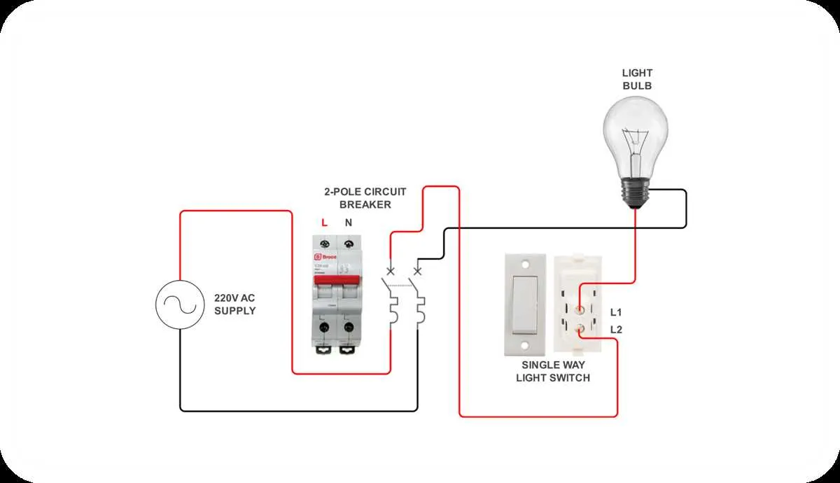
If you need to control a light from two different spots in a room, a straightforward method is using a dual-point control arrangement. This setup allows you to turn the light on or off from either location without complicating your wiring system.
First, make sure to understand the correct connections for the components. The two controlling devices should be connected in a way that allows a change in the flow of electricity between the light fixture and the power source, ensuring it can be manipulated from either position. In this arrangement, two control points are typically wired to a common terminal, with one of the points handling the flow of electricity and the other managing the on/off status.
For the light to function as expected, the power supply must be appropriately routed through both devices, with particular attention given to the placement of each component. This configuration works best when the light is positioned centrally and each point is easily accessible. Pay close attention to proper insulation and grounding during installation to avoid potential safety hazards.
Recommendation: Double-check your work with a multimeter after setup. Verify that the power is correctly flowing when toggling each of the two controllers. This will help you catch any issues early on before completing the installation.
By using this method, you’ll be able to enjoy the convenience of controlling the light from either position without running extra wires across the room. It’s a simple solution that doesn’t compromise safety or functionality.
Understanding a 3-Point Control System for Lighting
For effective control of a single light from two different locations, a 3-point control system is essential. This setup allows users to manage lighting from multiple spots, commonly seen in hallways or stairwells.
Follow these steps to set up the system correctly:
- Connect the power source to the first terminal of the first device.
- Use two travelers to link the first and second devices, ensuring each is properly connected to the second terminal of each point.
- The third terminal at both devices must connect to the light fixture, allowing power flow when either point is activated.
Key components of the system include:
- Power supply
- Traveler wires
- Light fixture
- Two control points
This configuration helps maintain flexibility in room or hallway lighting management. Ensure proper wiring to avoid issues with power flow or device malfunction.
How to Wire a 3 Way Switch for Controlling a Light from Two Locations

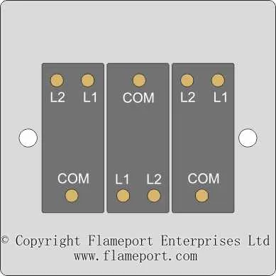
Start by ensuring that the power is turned off at the electrical panel. You’ll need two types of terminals: common and traveler. The common terminal on each device connects to the power source or the load, while the traveler terminals carry the current between the two units.
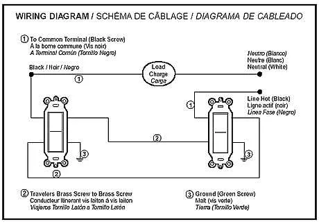
At the first unit, connect the black (hot) wire from the power supply to the common terminal. Then, connect two traveler wires to the traveler terminals. One of these wires should lead to the second device.
At the second unit, connect the traveler wires to the corresponding traveler terminals. The common terminal of this unit will be connected to the light fixture. Ensure the white (neutral) wire from the fixture is connected directly to the neutral bus bar at the panel. The ground wire should be attached to each device’s ground terminal.
Once everything is connected, double-check the wiring and secure the devices into their boxes. Turn the power back on and test the functionality by flipping each device in both directions to ensure that the light operates correctly from both locations.
Common Wiring Mistakes in Multi-Control Lighting Systems and How to Avoid Them

One frequent error is incorrect wire connection to the traveler terminals. Always ensure that the two traveler wires are correctly connected to the respective terminals on both control units. Reversing them will cause malfunction, preventing proper operation of the lighting system.
Another mistake is failing to connect the common terminal correctly. The common terminal must be connected to the incoming hot wire. Miswiring this can result in the light remaining permanently on or off, or cause an intermittent function.
Improper grounding is another issue that can lead to electrical hazards. Make sure to connect the grounding wire to the metal box (if applicable) and the grounding screw of both devices. This is essential for user safety and proper functioning of the setup.
A common wiring mistake is neglecting to check for correct voltage ratings when selecting components. Ensure that the switches and wires can handle the load of the lighting fixture, as using inadequate components can cause overheating or failure of the system.
Lastly, many individuals ignore the importance of turning off power at the breaker before starting any electrical work. This step is crucial to avoid electric shock and ensure the safety of the installation process.
Understanding the Role of Travelers in a 3-Wire Setup

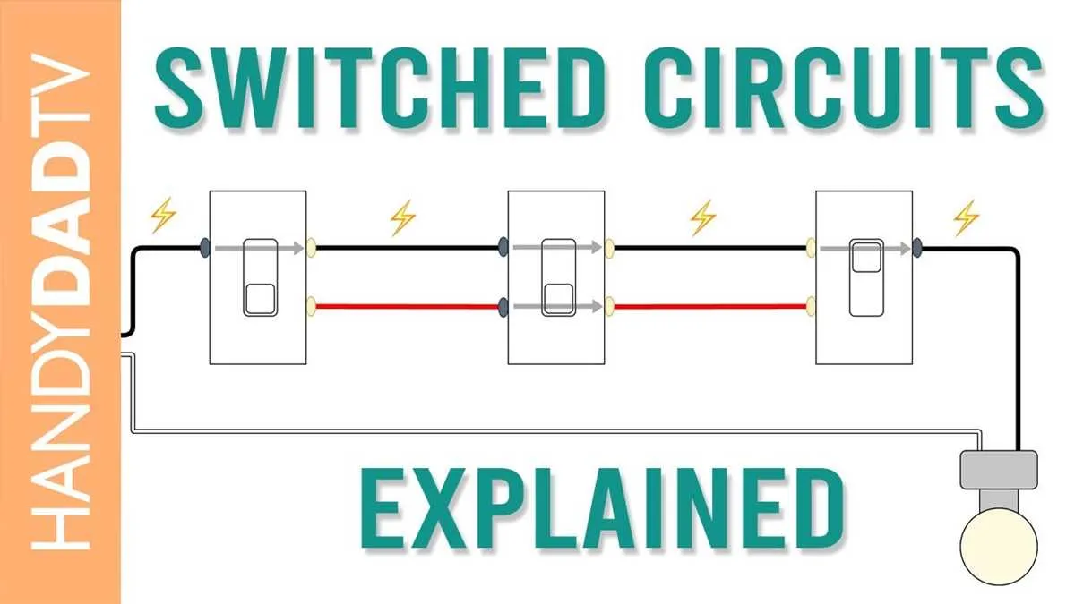
The travelers are crucial components in a setup where two control points manage a single load. These conductors enable the transmission of the current from one location to another, allowing for the alternating control of the device. Each traveler wire connects one point to another, facilitating the flow of power between them.
In such arrangements, two of the wires serve as travelers, while the third one acts as the common. It’s essential to note that these travelers carry the same current, switching back and forth depending on the positions of the controlling elements.
It’s important to connect the travelers correctly to ensure proper function. If wired incorrectly, the device may not respond to the controls as expected, leading to malfunction or failure to activate from one of the control points.
Key Tip: Make sure both travelers are connected to the corresponding terminals on the controlling devices, ensuring continuity in the path of the current. Always verify the connections before powering up.
When installing, check the quality of the connections, especially in locations where the wires may be exposed to wear. Any degradation in the quality of the traveler connections can affect the overall performance and reliability of the entire setup.