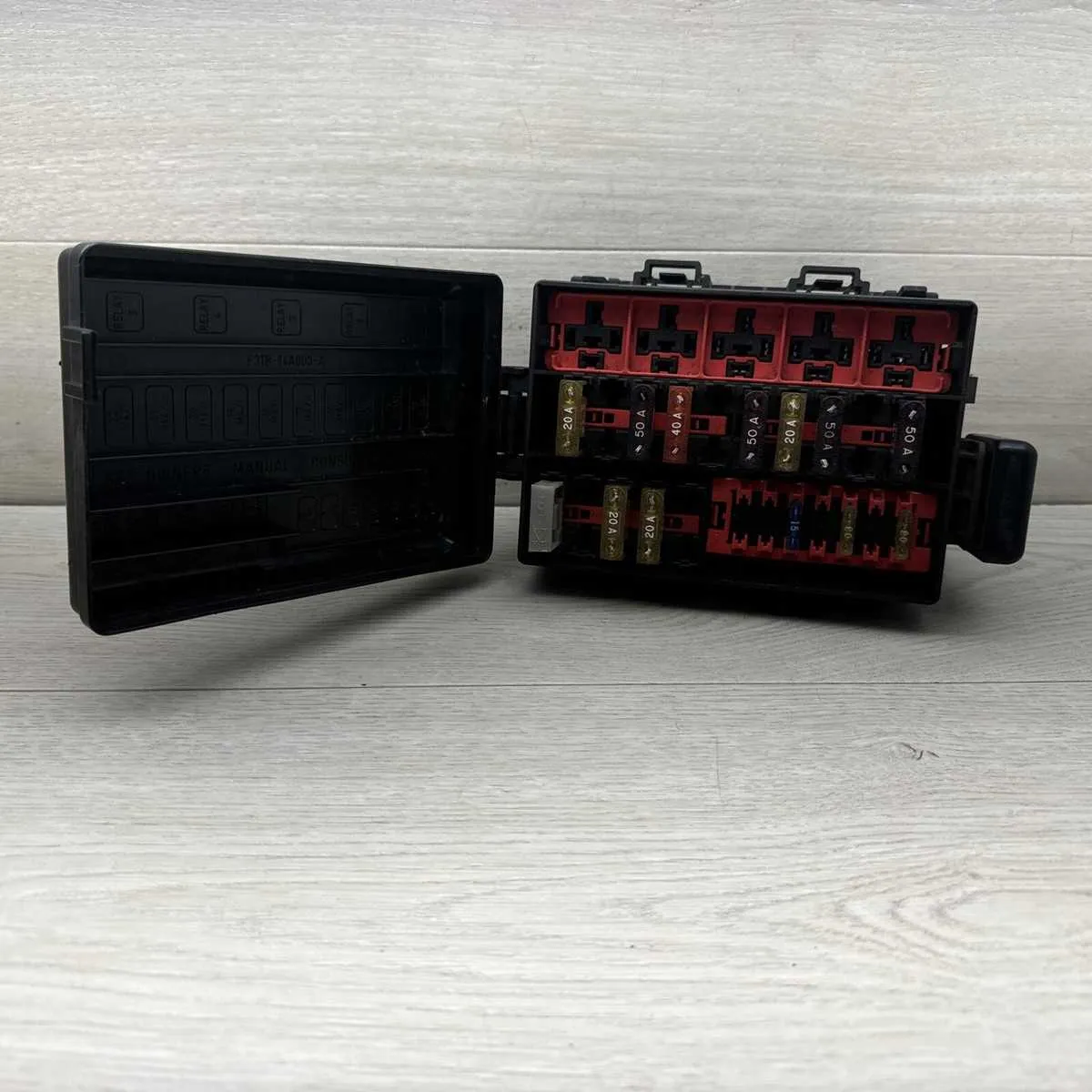
Locate the main panel beneath the steering column, slightly to the left. Remove the protective cover to access the grid. Each relay and miniature protector is numbered; cross-reference these digits with the legend printed on the back of the lid.
Position 2: tail lamps and running lights. Slot 4: instrument cluster backlight. Location 8: turn signal mechanism. Section 10: blower motor operation. Row 13: cigarette lighter and auxiliary power outlet.
If experiencing radio failure, inspect slot 11. For issues with power windows or seats, verify position 14. Starter problems often trace back to location 16, responsible for ignition control. Don’t overlook the under-hood relay block for high-load circuits such as ABS or headlamps.
Always disconnect the battery before inspecting or replacing components. Use a test light or multimeter to check continuity. Replace only with the specified amperage to avoid overload or damage.
Power Distribution Layout for Mid-’90s Ford Pickup
Locate the relay center under the dashboard on the driver’s side, adjacent to the kick panel. The top-left slot is typically assigned to the stoplamp circuit (15A), while the adjacent 10A unit safeguards the left tail and marker lights. The right tail lights are managed by a separate 10A piece positioned lower on the panel.
Engine control components are protected by a 20A unit near the center. Look for the 30A element dedicated to the blower motor in the lower-left quadrant. The ignition switch is shielded by a 15A component, generally positioned near the upper right.
The under-hood compartment holds high-amperage protectors. The starter relay relies on a 60A element; the ABS pump uses a 60A piece as well, located toward the passenger side. The headlamps are secured by two 20A units, one for each side.
Always verify amperage ratings stamped directly on each piece before replacement. Use a test light or multimeter to confirm voltage presence across terminals if a specific circuit is nonfunctional.
Location and Access Points of the 1996 F150 Fuse Box
Start by checking beneath the steering wheel–directly above the brake pedal. The main relay panel is mounted behind a small cover on the lower dashboard. No tools are required to reach it:
- Look for a plastic panel near the left kick panel; pull it outward to reveal the housing.
- Use your fingers to disengage the retaining clips–avoid using metal objects to prevent damage.
An auxiliary power block is located under the hood on the driver’s side, close to the firewall. To locate it quickly:
- Lift the bonnet and inspect the area next to the master cylinder.
- Identify a black rectangular casing secured with two plastic tabs–press both simultaneously to lift the lid.
Always disconnect the negative battery terminal before accessing any components to avoid short circuits.
Fuse Assignments and Functions for Each Slot
Check position 1 for the airbag module power supply; if the warning light stays on, inspect this area first.
Slot 2 manages the stoplamp circuit. If brake lights are unresponsive, replace the element located here.
Use position 3 to troubleshoot the instrument panel; gauge failures often trace back to this point.
In position 4, the wiper control gets its current. If wiping speed is inconsistent or nonfunctional, verify the connection here.
Check location 5 for the radio and audio memory power. A reset clock or radio that won’t hold presets usually indicates a blown unit here.
Slot 6 powers the turn signal system. Rapid blinking or failure to blink typically means an open circuit at this location.
Area 7 handles the horn relay input. Silence from the horn button should prompt inspection of this contact.
At position 8, trailer tow lamps receive their feed. Malfunctioning trailer lights often point to this source.
Location 9 supports the HVAC blower motor. If fan speeds are stuck or not working, replace the component here.
Slot 10 manages electronic shift controls for 4WD models. Inability to shift modes indicates trouble at this circuit.
Area 11 energizes the fuel pump relay. If the engine cranks but won’t start, verify continuity at this point.
Position 12 covers the cigarette lighter socket. No charging power for accessories often traces back here.
Slot 13 sends power to the backup lamps. No reverse light response signals a likely issue in this spot.
Use position 14 to troubleshoot power windows. If one or more switches are dead, start diagnostics here.
Check location 15 for the charging system lamp and alternator excitation. A battery light that stays on is often tied to failure in this slot.
How to Identify and Replace a Blown Fuse in a 1996 F150
Start by locating the panel containing the electrical protection components under the dashboard or near the engine compartment. Use a tester or visual inspection to find any damaged element with a broken metal strip or discoloration inside the transparent casing.
Before removing the defective unit, disconnect the battery to prevent shorts. Use a fuse puller or needle-nose pliers to carefully extract the faulty piece without damaging the holder.
Match the amperage rating printed on the replacement part with the original to maintain circuit safety. Insert the new element firmly into the slot, ensuring it sits flush and secure.
Reconnect the power source and verify that the previously non-functional system now operates correctly. If the new protector blows again immediately, check for underlying electrical issues such as shorts or overloaded circuits.