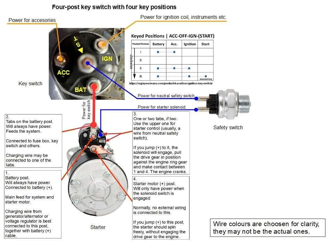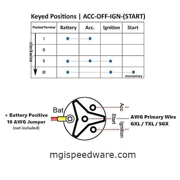
To ensure the proper functioning of a multi-purpose starting system, make sure to link each terminal to its designated component with accuracy. The main component should connect to the battery’s positive terminal. From there, create a secure path to both the engine control unit and the accessories, allowing seamless activation and deactivation.
Ensure the control terminal is properly routed to the power source and that all ground connections are tightly secured. Grounding is essential to avoid electrical interference or malfunction, and it helps minimize the risk of component failure. Check that the wire gauge corresponds with the expected current flow to prevent overheating.
For components like the starter motor, it’s critical to use heavy-duty cables capable of handling the load. Verify all terminals are clean, corrosion-free, and tightened to the recommended torque. If any component is showing signs of wear or damage, replace it immediately to prevent system failure.
Double-check that any security or anti-theft systems integrated into the setup are wired correctly, as this can affect the system’s ability to function smoothly. A multimeter can help you verify that power is properly reaching all points, ensuring reliable performance every time.
Tip: When in doubt, refer to the manufacturer’s specifications for precise guidance on wire placement and connections. Proper installation will significantly enhance the durability and functionality of the system, providing optimal results.
Connection Guide for a Versatile Starter Control

When installing a versatile starter control system, ensure proper connections to prevent electrical failures. Begin by identifying the main power lead, which typically connects to the battery’s positive terminal. This is crucial for providing energy to the rest of the setup.
Next, identify the terminal that handles the connection to the starter motor. This terminal is usually linked to a large wire that activates the motor when current is supplied. It is essential to check for a secure connection here to ensure proper motor function during activation.
The third terminal often serves as the ground connection. This should be connected securely to the vehicle’s metal frame or another grounding point to complete the circuit and avoid potential shorts.
Additionally, pay attention to the accessory terminal, which powers auxiliary components such as lights or radio. This lead should only be energized when the system is in the “on” position to avoid draining the battery unnecessarily.
Ensure that each connection is properly insulated and free of corrosion. Test all connections before final assembly to ensure reliable performance and safety.
For best results, always refer to specific manufacturer instructions, as configurations can vary slightly depending on the model.
How to Identify the Terminals on a Universal Ignition Switch
Begin by locating the back of the key-operated device. Typically, there are three main terminals to identify: the battery, the starter motor, and the accessory terminal. Each terminal corresponds to a specific function during the activation sequence.
The terminal closest to the body of the mechanism is usually for the battery connection. This is where the primary power source is connected. The second terminal is designated for the starter, engaging the motor to turn over the engine when activated. Finally, the accessory terminal is used to power additional components, such as lights or radios, when the key is turned to the accessory position.
To confirm correct identification, use a multimeter to test continuity between terminals and ensure each one activates as expected during the key’s rotation process. Always refer to the manufacturer’s specifications for accurate terminal identification as some devices may have variations in terminal placement or labeling.
Step-by-Step Guide to Connecting a Multi-Function Start Circuit to Your Vehicle

Start by ensuring the vehicle is turned off, with the key removed from the lock. Disconnect the battery to avoid accidental short circuits during installation.
Identify the terminals on the component. Typically, you’ll have four primary connections: two for power (positive and negative), one for accessory control, and one for the starter motor.
Attach the positive lead from the battery to the designated power input. This connection will supply energy to the system. Be sure to use a durable, insulated wire that can handle the required current.
The negative terminal should be connected to the vehicle’s chassis or any suitable ground point. This ensures proper return flow for the electrical system.
For the accessory terminal, connect it to components such as the radio, lights, or other devices that should activate when the system is in the “on” position. Use a wire that is rated for accessory load.
The last connection is the starter motor terminal. This wire should link to the motor’s solenoid, enabling the engine to turn over when the system is engaged. Ensure that this wire is heavy-duty to handle the high current necessary for starting the vehicle.
After all connections are secured, double-check the wiring and make sure the connections are tight and insulated. Reconnect the battery, and test the system. Turn the key to the appropriate positions to verify that each function works as expected.
If everything functions correctly, you can now securely mount the component in place, ensuring that it is positioned away from heat sources or moving parts. Ensure all wires are well routed to prevent any abrasion or interference with other vehicle systems.
Troubleshooting Common Electrical Issues with Multi-Function Start Mechanisms
If your vehicle fails to start, or exhibits erratic behavior, there may be a simple solution to fix the problem. Follow these steps to address common issues with the electrical components of start systems:
- Check the Power Source: Ensure that the battery is fully charged. A weak or dead battery is often the main culprit. Use a multimeter to verify voltage levels.
- Inspect the Connections: Loose or corroded terminals can cause intermittent power loss. Clean the connectors and tighten them to ensure reliable operation.
- Test the Fuse: Blown fuses can disrupt power flow. Identify the relevant fuse for the starting system and replace it if necessary.
- Verify the Relay: A faulty relay can prevent current from reaching critical components. Check for proper relay activation and replace if needed.
- Check the Neutral Safety Switch: The vehicle may not start if the system doesn’t detect the transmission is in ‘Park’ or ‘Neutral’. Ensure the switch is correctly aligned and functioning.
In addition to the steps above, ensure that no exposed wires are causing short circuits. Any sign of wear or damaged insulation should be addressed immediately to prevent further issues.
- Confirm the Start Button Operation: If the button is faulty, no current may reach the starter motor. Test the button’s continuity or replace it.
- Inspect the Starter Motor: A malfunctioning starter motor can hinder the entire process. Listen for unusual sounds like grinding or a lack of any noise when attempting to start.
Follow this checklist systematically, and you’ll be able to isolate the problem and restore reliable performance to your start system.