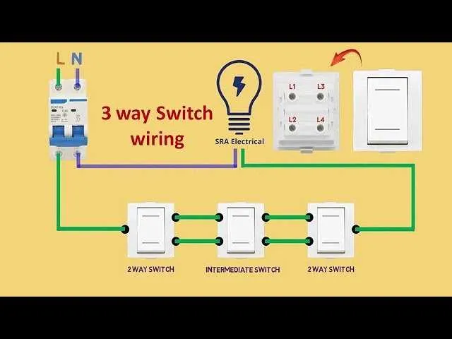
To set up a circuit with control from two locations, ensure you understand the essential components required: two control points, one light fixture, and the correct wiring method. Begin by installing the first and second controllers at opposite ends of the room, ensuring that each one has an electrical box for proper mounting.
Next, use traveler wires to connect the terminals of the controllers. These wires allow the current to flow between the control points and regulate the light’s state. The power source should be connected to one of the terminals on the first controller, with the common terminal wired to the light fixture. The other controller should then connect to the same light fixture, ensuring the circuit allows for control from both ends of the space.
For safety and efficiency, it is crucial to correctly wire the common terminal on both controllers. This will prevent short circuits and allow smooth operation of the setup. Double-check your connections and verify that the correct terminals are used for the travelers and common wires, as errors in these steps can lead to malfunction.
Following these steps will provide a reliable and functional system, ensuring you can control your light from multiple locations with ease. Proper installation not only guarantees functionality but also enhances safety throughout your setup.
Wiring Circuit for Two-Control Light Setup
To correctly wire a two-control lighting system, follow these detailed steps:
- Power Source Connection: Connect the live wire from the power source to the first control unit. Ensure the ground wire is properly attached to the grounding point.
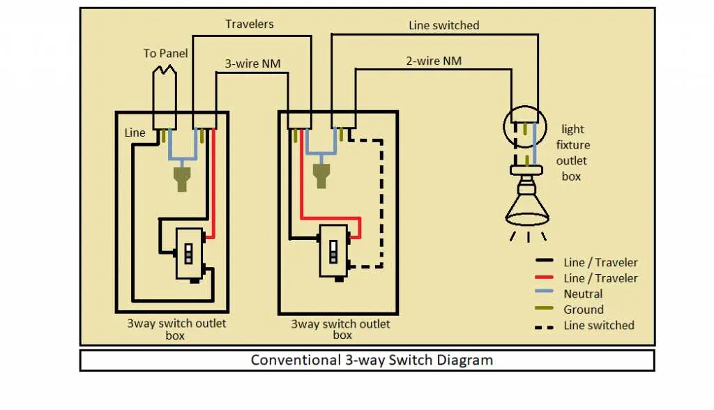
- Linking the First and Second Controllers: Use a 3-wire cable to connect the terminals of both controllers. This includes a common wire (typically black), a traveler (red), and a neutral (white). Make sure the travelers are attached to the corresponding terminals of each unit.
- Load Connection: Attach the load (light fixture) to the common terminal of the second unit. This terminal controls the flow of electricity when the light is to be turned on or off.
- Finishing the Circuit: Complete the circuit by connecting the neutral wire from the power source directly to the light fixture. Ensure all connections are secure and insulated.
To troubleshoot, check the following:
- Confirm the common wire connections on both controllers are accurate.
- Ensure the travelers are properly wired to each terminal as required.
- If the light doesn’t respond to both controllers, check the connections at the load terminal and ensure it’s receiving power from both units.
This wiring setup allows for controlling a light from two different locations, providing flexibility and convenience in larger spaces.
Understanding the Wiring Connections for 3-Way Switches
To properly wire a multi-way control setup, you need to connect two devices in a way that allows the control of a single light from two distinct locations. The first device, typically the main unit, has a common terminal, while the second, secondary unit, includes traveler terminals. These connections ensure the current can flow through the devices depending on their position.
The common terminal of the first unit is connected to the power source or the light fixture. The traveler terminals are linked with the corresponding terminals of the second device, where the current is directed to complete the circuit. Ensure you correctly wire the neutral and ground connections, as improper grounding may cause safety hazards.
Pay close attention to the wire types used. Black wires usually indicate live connections, while white wires are neutral. A red wire is typically used for the traveler, marking its path through the circuit. Double-check all connections for tightness and correctness, as loose or incorrect wiring could lead to malfunction or electrical fires.
Lastly, when testing the circuit, ensure that each device functions independently to control the lighting. The first unit should be able to turn the light on or off, and the second unit should also toggle the light’s state, regardless of the position of the first unit. Proper installation allows for reliable, two-point control of your lighting system.
Common Mistakes in 3-Wire Circuit Installation

Incorrect wire connections are one of the primary issues when setting up a multi-control lighting system. It’s essential to correctly identify the traveler and common terminals. Misplacing wires on these can result in malfunctioning controls or complete failure to operate.
Using the wrong type of cable for the installation is another frequent mistake. Always use NM-B 14/3 or 14/2 with ground cable for a three-way configuration. Using a two-wire cable will prevent proper operation, as it lacks the necessary traveler wire.
Not following the proper grounding procedure can lead to dangerous situations. Ensure that all metal boxes are grounded and that each fixture is properly bonded. Failure to do so compromises the safety of the entire system.
Failing to test functionality before closing up the electrical box is another common error. Always verify that both controls work correctly in all positions before securing any panels. Testing helps prevent rework and potential issues down the road.
Confusing the common terminal with traveler terminals is a common pitfall. The common terminal must be connected to the power supply wire, while the traveler terminals handle the connections between the two controls. Double-check the manual to avoid this mistake.
Overlooking wire insulation is another issue that can cause short circuits or fires. When making connections, ensure that all wire ends are stripped just enough to fit under the terminal screw, without exposing excessive bare wire.
Not using the correct tool to tighten terminal screws can lead to loose connections. A torque screwdriver is recommended to apply consistent pressure, preventing over-tightening or under-tightening, both of which can cause electrical hazards.
Step-by-Step Guide to Troubleshooting 3-Way Circuit Issues

Start with Power: Before touching any components, disconnect the power at the breaker panel. Verify using a non-contact voltage tester that there is no current at the connections.
Check for Loose Connections: Inspect both terminals on each device involved. Loose or unconnected wires are often the cause of malfunction. Tighten any loose screws or reattach wires that are disconnected.
Examine the Wiring for Short Circuits: A short between the hot and neutral wires can disrupt proper operation. Use a multimeter to check for continuity between the terminals and any exposed metal parts. If continuity exists, address the short immediately.
Test the Components Individually: If the circuit remains unresponsive, test each device individually. For example, replace one of the controlling units with a known working one. If the circuit works after this step, the faulty device is likely the issue.
Verify Compatibility: Ensure all components are compatible with each other. Different brands or models might have varying internal wiring schemes, leading to malfunction if not correctly matched.
Inspect the Traveler Wires: These are often the source of many issues. Ensure that the traveler wires are correctly connected between both devices. A reversed traveler wire can result in an operational failure.
Confirm Proper Grounding: Check that the ground wire is securely connected at all points. An improper or missing ground can lead to erratic behavior or complete circuit failure.
Use a Multimeter for Voltage Testing: Once you’ve checked for physical issues, turn the power back on and measure voltage at various points along the circuit. A lack of voltage where it should be present indicates a deeper wiring issue.
Test for Proper Continuity: After verifying power, use your multimeter to test for continuity between the terminals when the device is toggled. Lack of continuity indicates faulty internal components.
Look for Damaged Wires: Examine the wire insulation for visible damage. A frayed wire may cause an intermittent connection, leading to malfunction. Replace any damaged wires.
Check for Electrical Overload: Overloading the circuit can lead to disruptions. Verify the power rating of the devices connected to ensure it does not exceed the circuit’s capacity.
Replace Faulty Parts: If troubleshooting reveals any faulty components that cannot be repaired, replace them with identical models that are rated for the circuit’s power requirements.