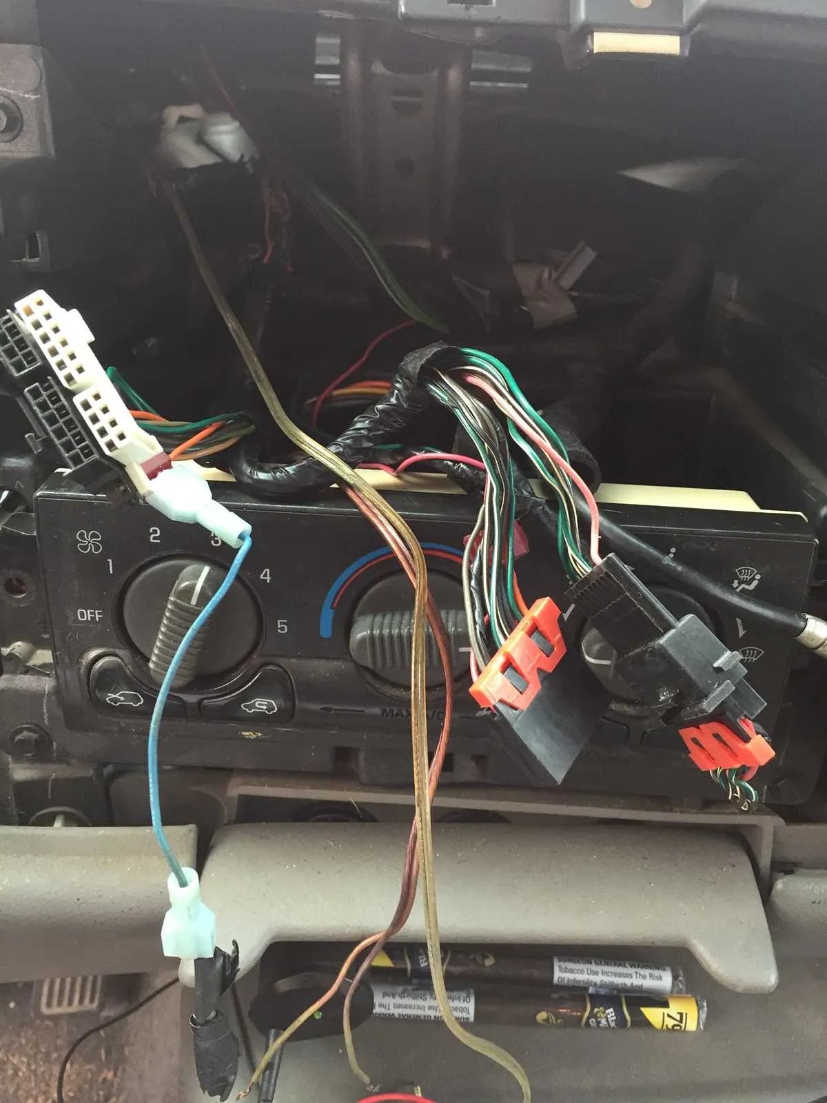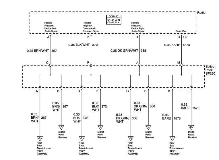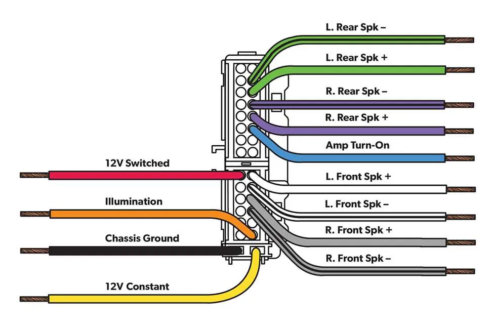
For those looking to install or troubleshoot an in-car audio system, it’s crucial to have an accurate blueprint for connecting the components. The first step is ensuring proper power supply to the unit and that the ground connections are securely established. Failure to do so can result in malfunction or even damage to the equipment.
Next, the speaker outputs must be routed correctly, as improper configuration can lead to sound distortion or no audio output at all. Use color-coded cables to match the connections specified in the vehicle’s manual, ensuring each speaker is wired to the corresponding port on the device. This minimizes the risk of errors and ensures optimal sound performance.
Don’t forget to double-check the antenna connection, as a loose or improperly connected antenna can result in poor reception or total loss of signal. It’s also recommended to use high-quality connectors to ensure long-term reliability and prevent any corrosion issues over time.
Important tip: Always disconnect the vehicle battery before starting the installation to prevent any electrical short circuits or unexpected voltage surges. Once the system is fully connected, test all functions thoroughly to confirm everything is working as expected.
Remember: Even if you’re an experienced installer, taking the time to verify every connection can save you from costly repairs and troubleshooting down the line.
Electrical Connections for Car Audio System
For proper installation of your vehicle’s sound system, start by identifying the key terminals: power, ground, illumination, and speaker outputs. Ensure the red wire is connected to the ignition-controlled 12V source, while the black wire should go to a solid grounding point on the car’s frame. The orange wire is typically used for the illumination connection, activating lighting when the car’s lights are turned on.
For the speaker wires, match the color codes: typically, white and white with black stripes for the front left, gray and gray with black stripes for the front right, green and green with black stripes for the rear left, and purple and purple with black stripes for the rear right. Properly securing each connection with a reliable terminal or crimp ensures stable performance and prevents short circuits.
Always double-check wire integrity and ensure that no wires are exposed to prevent shorting. Additionally, use a multimeter to verify voltage on power and ground lines before completing the installation. This ensures safe and effective operation of the sound system without damaging any components.
Understanding the Pinout Connections for the 2001 Chevy Tahoe Radio

For proper installation and troubleshooting of the audio system in your vehicle, it is crucial to understand the connection layout and functions of each pin on the stereo connector. Here’s a breakdown of the essential pins and their respective functions:
- Pin 1: Ground (Black) – This pin connects to the vehicle’s chassis to ensure the proper flow of electrical current and prevent shorts.
- Pin 2: Power (Yellow) – Supplies constant 12V power to maintain settings such as time and preset stations even when the car is off.
- Pin 3: Ignition Power (Red) – Powers the unit when the ignition is turned on, allowing the audio system to activate.
- Pin 4: Amplifier Power (Blue) – Used for external amplifier connections, providing the necessary voltage to power external speakers or amplifiers.
- Pin 5: Illumination (Orange) – Controls the backlight on the display, adjusting brightness in response to the vehicle’s lighting system.
- Pin 6: Dimmer (Gray) – This pin manages the dimming function when the dashboard lights are adjusted, reducing display brightness in low-light conditions.
- Pin 7: Front Left Speaker (+) (Green) – Transmits positive audio signals to the front left speaker.
- Pin 8: Front Left Speaker (-) (Green/Black) – Sends the negative audio signals to the front left speaker.
- Pin 9: Front Right Speaker (+) (Gray) – Delivers positive audio signals to the front right speaker.
- Pin 10: Front Right Speaker (-) (Gray/Black) – Sends negative audio signals to the front right speaker.
- Pin 11: Rear Left Speaker (+) (Purple) – Carries positive audio signals to the rear left speaker.
- Pin 12: Rear Left Speaker (-) (Purple/Black) – Transfers negative audio signals to the rear left speaker.
- Pin 13: Rear Right Speaker (+) (White) – Transmits positive audio signals to the rear right speaker.
- Pin 14: Rear Right Speaker (-) (White/Black) – Sends negative audio signals to the rear right speaker.
- Pin 15: Antenna (Blue/White) – Provides a signal for the antenna to raise when the audio system is powered on.
- Pin 16: Subwoofer (+) (Purple/White) – Supplies positive audio signals to an external subwoofer for enhanced bass output.
- Pin 17: Subwoofer (-) (Purple/Black) – Sends the negative audio signals to an external subwoofer.
By matching these connections correctly, you ensure proper functionality of the sound system, as well as avoid potential damage to the internal components. Always use high-quality connectors and wiring to guarantee a stable and reliable connection.
How to Identify and Repair Common Electrical Issues in the Audio System

Start by inspecting the fuse box. A blown fuse is one of the most common reasons for power loss in the audio equipment. Locate the fuse related to the sound system and test it with a multimeter. If it shows no continuity, replace it with a fuse of the same rating.
Next, check the connections at the back of the unit. Loose or corroded connectors can interrupt power supply or cause poor signal quality. Ensure all connectors are securely attached and clean any corrosion with a contact cleaner.
Pay attention to the ground connection. A poor ground can lead to distorted sound or complete failure of the system. Examine the grounding point for any signs of rust or dirt, which could impede the flow of electricity. Clean or reattach the ground wire if necessary.
If the unit powers on but no sound is heard, inspect the speaker wires. Over time, they may become frayed or disconnected. Trace the wires to ensure they are intact, with no breaks or loose connections. Reconnect or replace any damaged sections.
Lastly, if the system continues to malfunction, test the internal components of the unit. Faulty components like capacitors or resistors can lead to complete system failure. Use a circuit tester to check for any defective parts and replace them accordingly.
Step-by-Step Guide to Installing Aftermarket Audio System in a 2001 SUV
Start by disconnecting the vehicle’s negative battery terminal to prevent any electrical shocks or damage. This is a crucial safety step when working with electrical components.
Remove the factory stereo unit by using a trim removal tool to carefully pry off the dashboard panel. Once the panel is detached, unscrew any fasteners securing the existing unit in place.
After the old unit is out, carefully disconnect the harness and antenna plug. Inspect the wiring connections and verify they match the adapter harness provided with the aftermarket system.
Connect the adapter harness to the vehicle’s original wiring, ensuring each wire is correctly matched: the power, ground, speaker, and antenna connections. Use electrical tape or heat shrink tubing to secure any exposed wires to avoid short circuits.
Before securing the new unit, test the system by reconnecting the vehicle’s battery. Turn on the ignition and check if the new system powers up and responds to inputs like volume and channels.
Once verified, slide the new unit into place and secure it with screws. Reattach the dashboard panel and ensure everything is flush with the surrounding trim.
Finally, perform a final check of all audio functions, ensuring speakers are working correctly and the system integrates seamlessly with the vehicle’s other features.