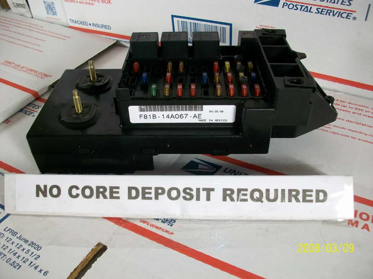
Locate the power distribution center under the dashboard on the driver’s side to quickly identify the exact position of each circuit protector. This unit controls critical electrical components including lighting, ignition, and climate control systems.
Refer to the onboard label for precise identification of each slot to avoid confusion during troubleshooting. The labeling indicates amperage ratings and corresponding vehicle functions, which ensures correct replacements and prevents electrical failures.
For maintenance or replacement, always disconnect the battery before accessing the circuitry hub to eliminate risk of shorts or shocks. Use a reliable multimeter to verify continuity and assess which conductor requires service.
Detailed schematics are vital for diagnosing malfunctions in auxiliary power and safety devices. Understanding this layout minimizes downtime and guarantees accurate repairs without unnecessary component swaps.
Electrical Relay and Fuse Layout for the 2001 Ford F150

Locate the primary distribution box under the dashboard on the driver’s side for access to the main electrical protection units. The compartment houses blade-type protectors rated from 10A to 30A, each responsible for circuits such as lighting, ignition, and auxiliary power.
Consult the identification chart on the underside of the access cover to match each slot with its designated function. Key circuits include the headlamp circuit protected by a 15A protector, the power windows with a 30A safeguard, and the horn powered through a 20A unit.
For engine management components, find dedicated slots with medium amperage safeguards, usually 20A, positioned near the relay box. These ensure safety for fuel injection and ignition coil circuits.
When replacing a faulty unit, always use an exact amperage match to prevent electrical damage or circuit failures. Employ a fuse puller tool for safe removal and insertion to avoid terminal damage.
Secondary distribution box is located within the engine compartment close to the battery. It contains higher capacity protectors for the cooling fan, ABS module, and air conditioning system, typically ranging from 30A to 50A.
Locating and Identifying Each Fuse in the 2001 Ford F150 Panel
Begin by opening the cover of the main electrical distribution box situated under the dashboard on the driver’s side. Inside, a label details every circuit protector with corresponding amperage ratings and exact positions. For easy identification, use the printed guide on the inside of the lid, which correlates each slot with its function, such as headlights, horn, or power windows.
Each circuit breaker and blade-type protector is numbered, typically from left to right and top to bottom. Match these numbers with the reference sheet to determine the precise role of each component. For example, slot #12 often governs the ignition system, while slot #5 handles auxiliary power outlets.
To avoid confusion, use a tester or fuse puller tool included in the kit to check each unit’s integrity before replacement. Look for any discoloration or broken filaments indicating a malfunction. Always replace with the exact amperage rating indicated on the reference guide to prevent electrical issues or damage.
Additionally, an under-hood distribution box contains higher-current protectors for critical systems like cooling fans and ABS. This second box follows a similar layout with clear labeling inside the cover, facilitating quick verification and service.
Understanding the Function of Each Fuse and Circuit Protection
Identify the amperage rating of every protective device to ensure it matches the circuit requirements; for instance, a 15-amp breaker safeguards lighting circuits, preventing overloads without nuisance trips. Powertrain control modules rely on dedicated 10-amp safeguards, isolating critical electronics from voltage spikes and short circuits.
Recognize that relay-operated circuits, such as those controlling fuel pumps or cooling fans, include inline breakers that act as fail-safes against electrical faults while maintaining continuous operation under normal conditions. Ignoring these can lead to erratic component behavior or permanent damage.
Use a multimeter to test continuity and voltage drop across each protective element regularly; a faulty protector may show open circuits even if visually intact. Replace any unit showing irregular readings with an equivalent rating to maintain system integrity.
Power distribution blocks in the engine compartment include multiple protective devices segregated by function–engine management, lighting, HVAC systems, and auxiliary power. Understanding their exact location helps in troubleshooting electrical failures swiftly and accurately.
Always refer to the vehicle’s electrical manual to correlate each circuit protector with its specific subsystem to avoid accidental disablement of essential safety features like airbags or ABS modules.
Step-by-Step Guide to Replacing and Testing Electrical Protectors in Your Truck
Always disconnect the battery before handling any electrical components to avoid shorts or shocks. Use a proper tester to check each protector’s integrity before replacement.
- Locate the protective device box under the dashboard or hood, referring to the specific layout for your model year and engine type.
- Identify the faulty circuit by checking the symptoms or using a diagnostic tool that pinpoints electrical failures.
- Remove the defective safety link using a fuse puller or needle-nose pliers, ensuring no damage to surrounding components.
- Inspect the removed protector for a broken filament or discoloration, signs of failure.
- Match the replacement part’s amperage rating exactly with the original to maintain circuit protection integrity.
- Insert the new protector firmly into its slot, making sure it is seated properly to avoid loose connections.
- Reconnect the battery and activate the affected system to confirm restoration of function.
- If problems persist, test the new protector with a multimeter set to continuity mode; no beep indicates a defective unit or wiring issue.
Regularly inspect the electrical safeguard box for corrosion, moisture, or debris to prevent premature failures and maintain reliable circuit protection.