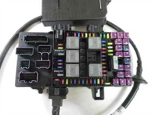
Locate the main power distribution center beneath the dashboard on the driver’s side to access the circuit protection elements efficiently. Each slot within this unit corresponds to a specific system component, ensuring optimal vehicle functionality and safety.
Consult the owner’s manual or official maintenance guides for precise allocation of each protective element, as the arrangement may vary slightly depending on trim and optional packages installed.
For troubleshooting electrical issues, verify the status of relays and circuit protectors housed in the passenger compartment’s access panel. Pay special attention to components controlling lighting, ignition, and climate control systems, as these are critical for vehicle operation.
Regular inspection and replacement of blown units can prevent unexpected malfunctions and ensure continued reliability of the electrical system.
Vehicle Electrical Panel Layout for the 2004 Expedition Model
Locate the main power distribution center beneath the dashboard on the driver’s side for quick access. Reference the detailed layout to identify each circuit protector by number and function.
- Position 1: Headlight relay control – critical for nighttime visibility
- Position 5: Ignition system protection – prevents overload in starting circuits
- Position 8: Air conditioning compressor relay – safeguards climate control operation
- Position 12: Radio and audio system feed – ensures uninterrupted entertainment power
- Position 20: Power windows and door locks – protects convenience features
To diagnose electrical issues efficiently:
- Identify the malfunctioning component
- Match it to its corresponding slot in the under-hood or cabin fuse center
- Use a test light or multimeter to check continuity
- Replace the protector with an identical amperage rating if blown
Always disconnect the battery before servicing the panel to avoid short circuits or injury. Consult the owner’s manual for exact location references and amperage specifications to maintain optimal vehicle safety and functionality.
Locating the Electrical Panel Compartments
The primary panel is situated beneath the dashboard on the driver’s side, close to the left kick panel. Access requires opening a small plastic cover that snaps off easily for inspection or replacement of components.
An additional distribution unit is found in the engine compartment, near the battery and firewall area. This exterior compartment contains larger capacity circuit protectors and relays essential for engine management and high-current circuits.
For maintenance or troubleshooting, always disconnect the main power source before accessing these units to avoid electrical hazards. Clear labeling inside each compartment aids in identifying the relevant switches and connectors.
Identifying and Understanding Fuse Functions
Locate the electrical panel’s legend inside the cover or in the owner’s manual to match each protective element with its corresponding circuit. Each element safeguards a specific system, such as lighting, ignition, or climate control.
Check the amperage rating stamped on each component to ensure it matches the required specification for the protected device. Using a rating too high risks wiring damage, while a lower rating may cause unnecessary interruptions.
Differentiate between circuits by their labels: terms like “A/C,” “Radio,” or “Power Outlet” indicate the area of protection. This helps in troubleshooting electrical failures by pinpointing which segment is disabled when a component trips.
Replace blown elements only with exact matches to maintain circuit integrity. Avoid using makeshift solutions or higher-rated parts, which can lead to overheating or fire hazards.
Regularly inspect connectors for corrosion or loose fittings to prevent intermittent power loss. Proper seating of these protective devices ensures consistent performance of all monitored systems.
Replacing and Testing Fuses Safely
Always disconnect the vehicle’s battery before removing any electrical protection components to prevent shorts or shocks. Use a reliable multimeter set to continuity mode to verify the integrity of each circuit protector before installation.
Replace a blown element only with one that matches the exact amperage rating specified by the manufacturer to avoid electrical fires or damage to wiring. Avoid using makeshift substitutes or higher-rated replacements.
When extracting a defective unit, employ a dedicated plastic fuse puller or insulated tweezers to minimize risk of accidental contact with live terminals. Inspect the protective holder for corrosion or melted plastic, which may indicate underlying issues.
After installation, reconnect the power source and test all related systems to ensure proper operation. If a newly installed unit blows again immediately, further diagnostic investigation is required to locate short circuits or faulty components.
Never attempt repairs with wet hands or in damp environments to reduce the risk of electric shock. Store spare elements in a clean, dry container away from extreme temperatures to maintain reliability.