When designing an audio system, achieving optimal sound performance requires a precise connection layout for both low-frequency drivers and high-frequency transducers. If you are aiming for balanced output, a proper arrangement of components is essential. This ensures each unit operates within its specified range, avoiding distortion or potential damage.
To maintain the integrity of sound reproduction, always ensure that the impedance levels of the components are matched correctly. Incorrect connections can cause power loss or unbalanced sound output. When arranging the links, use high-quality conductors to minimize signal degradation and interference. Be mindful of the distances between connections, as longer cables can reduce overall efficiency.
Investing time in understanding the relationship between each component and its role within the system will pay off significantly in audio clarity and system longevity. The goal is always to achieve a clean, powerful sound without overloading or underutilizing any part of the setup.
Connection Layout for High-Frequency and Bass Drivers
To ensure optimal performance, always connect the low-frequency unit to the amplifier’s output with thick gauge wire, while the high-frequency component should be linked through a capacitor in series. This prevents the lower frequencies from reaching the high-range speaker, safeguarding its components.
- Use a crossover to separate signals between drivers efficiently.
- Ensure the capacitor value matches the recommended range for the high-frequency unit, typically between 4uF and 12uF.
- Maintain a clean connection to avoid any signal degradation due to oxidation or loose fittings.
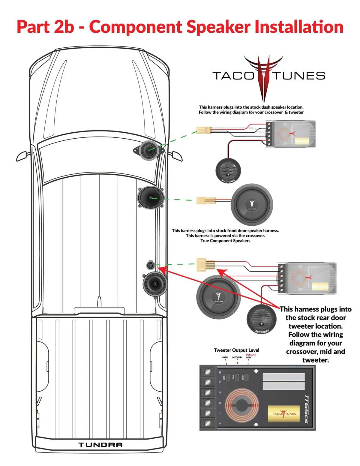
- Wire the low-frequency driver to the amplifier first, then link the high-range speaker through the crossover filter.
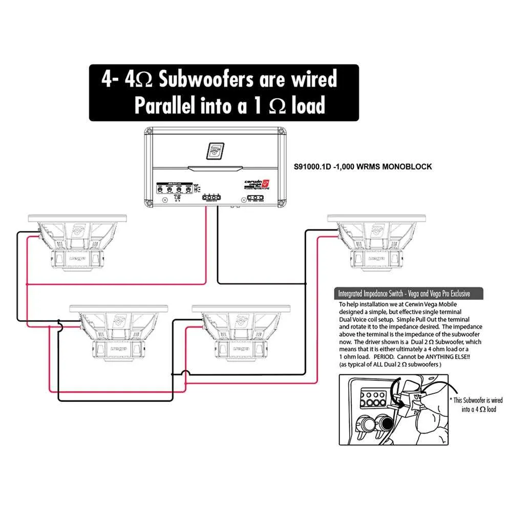
For dual-driver setups, the high-range unit should be connected after the crossover, with the low-range connected directly to the main amplifier. Be mindful of the impedance balance between the two drivers to avoid power mismatches.
- Connect the negative terminal of the low-range driver to the amplifier’s ground.
- Use the crossover to filter the high-pass signal, sending it to the positive terminal of the high-frequency unit.
- Test the system with a low volume to check for any distortion or malfunction in either unit.
Finally, verify that both drivers are in phase for coherent sound output. This is particularly important when using multiple units to ensure proper signal alignment and avoid phase cancellation.
Correctly Connecting Drivers in a 2-Way System
To achieve optimal performance, connect the low-frequency driver to the amplifier directly, ensuring the proper phase alignment. The high-frequency unit should be routed through a capacitor in series to filter out unwanted lower frequencies. This capacitor’s value typically ranges from 2µF to 12µF, depending on the crossover point you choose (usually between 2kHz and 5kHz). The low-pass filter for the bass driver is typically a coil, which should be placed in series with the speaker to block higher frequencies.
Ensure that both drivers share a common ground and are connected securely. Pay attention to impedance matching; commonly, 4-8 Ohm ratings are used. A mismatch can result in lower efficiency or potential damage to the system. Double-check all connections to avoid signal loss or distortion, especially at the crossover stage where accuracy is key.
To ensure proper phase coherence between the two units, it’s important to test the system once connected. If there is a lack of clarity or muddiness, adjust the component values in the filters or check for reversed connections that could lead to phase cancellation.
How to Connect Drivers to a Crossover Network

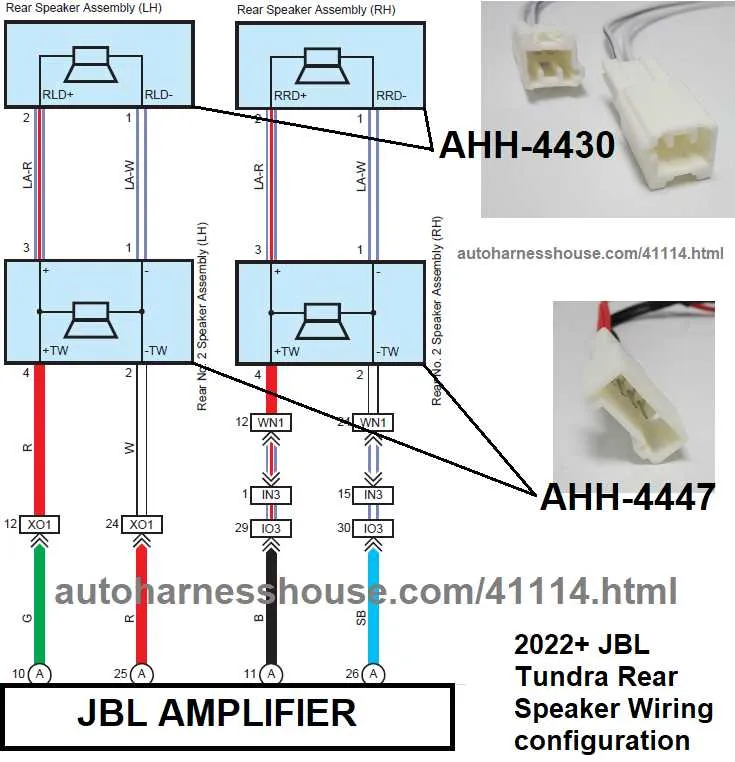
Start by ensuring that the crossover network is designed for the impedance rating of the drivers. Common values are 4 ohms or 8 ohms. Connect the positive terminal from the amplifier to the input of the network. Then, connect the output terminals of the crossover to the appropriate drivers: one output for the low-frequency and another for the high-frequency unit. It is crucial to use proper gauge wire to avoid power loss or distortion.
For the high-pass section, connect the positive output from the crossover to the high-frequency unit’s positive terminal, ensuring correct polarity. The negative terminal should be connected to the common ground. Repeat the process for the low-pass output, linking it to the low-frequency driver with attention to polarity and solid connections to ensure efficient energy transfer.
Verify that all components, such as capacitors or inductors in the network, are rated for the power you plan to use. Incorrect values can cause underperformance or damage. After completing the connections, test the setup with a low-volume signal to check for phase issues or distortion. If any issues arise, double-check the component ratings and connections.
Identifying and Solving Common Connection Issues in Audio Systems

Check the polarity of your connections. Incorrectly matched positive and negative terminals can lead to phase cancellation, reducing sound clarity. Ensure that the positive lead from the amplifier goes to the positive terminal on the driver unit and the corresponding connection on the high-frequency unit.
Inspect the cable integrity. Damaged or worn-out wires can cause poor signal transmission, resulting in distorted or no sound output. Use quality, durable cables and replace any frayed or cut sections immediately.
Verify the impedance match. Mismatched impedance between the amplifier and your connected components can lead to reduced efficiency or even damage. Always confirm that the impedance rating of the driver unit matches the output capacity of your amplifier.
Confirm proper crossover setup. An incorrectly configured crossover can send incorrect frequencies to either the low or high-frequency driver, leading to muddled or unbalanced sound output. Make sure the crossover frequency is properly set according to the specifications of both units.
Look for grounding issues. Ground loops or poor grounding can introduce hums or buzzes in your setup. Ensure that all components are properly grounded to avoid these unwanted noises.
Ensure tight and secure connections. Loose connections can result in intermittent audio or signal loss. Regularly check terminals for signs of wear or looseness and tighten them when needed.