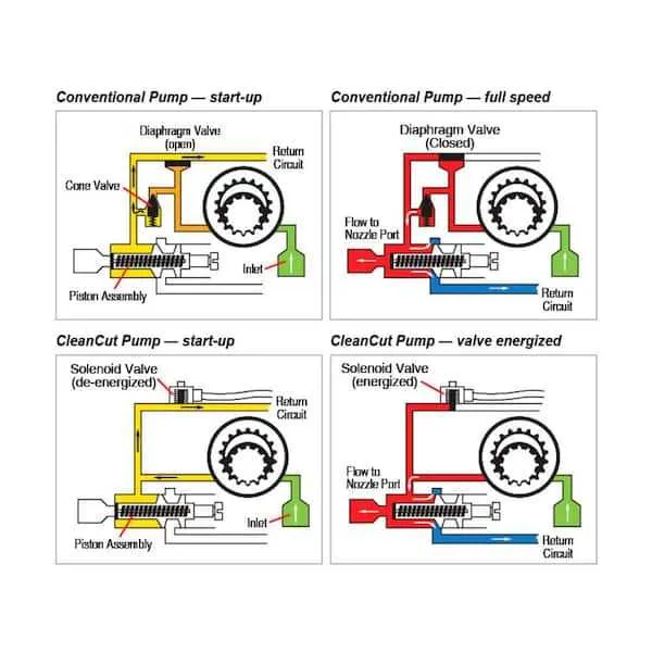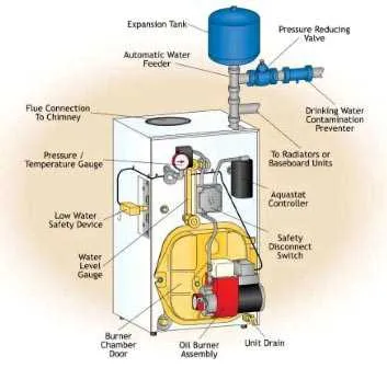
For efficient maintenance, it is crucial to familiarize yourself with the essential elements of the combustion assembly. Each part plays a specific role in the functioning of the system, and knowing how they interact helps prevent common malfunctions and ensures optimal performance.
Ignition components are typically the first to examine during troubleshooting. These include the electrode, which creates the spark necessary to start the combustion process, and the transformer that supplies the required voltage. Pay attention to the cleanliness of these parts to avoid weak or failed ignitions.
Another critical area to inspect is the fuel delivery system, consisting of the pump and nozzle. The nozzle’s opening must be free from clogs, as this affects the spray pattern and fuel efficiency. Ensure that the pump is delivering fuel at the correct pressure for consistent operation.
Lastly, check the ventilation mechanism, which includes the fan and exhaust system. A blocked or malfunctioning fan can lead to incomplete combustion, reducing efficiency and causing safety issues. Regular inspection and cleaning of the fan blades are essential to maintain airflow and system safety.
Understanding the Components of a Fuel Heating System
Ensure correct installation and maintenance of the following crucial elements for optimal operation of your heating system:
1. Combustion Chamber: The core area where the fuel mixes with air and ignites. Regular cleaning of soot and debris from the chamber ensures efficient combustion and prevents overheating.
2. Fuel Pump: Responsible for transporting the liquid fuel to the combustion area. If malfunctioning, it may cause inconsistent fuel delivery, leading to poor performance or failure. Check the pump’s pressure regularly to maintain proper flow.
3. Electrodes: These generate the spark required to ignite the fuel-air mixture. Replace any electrodes that show signs of wear, corrosion, or damage to prevent ignition failure.
4. Nozzle: Controls the amount of fuel and its spray pattern, essential for proper combustion. A clogged or worn nozzle should be replaced to avoid uneven fuel distribution.
5. Fan: Ensures proper air circulation for combustion. Dirty or obstructed fans will reduce air flow, resulting in incomplete combustion. Keep fans clean and inspect for mechanical issues.
6. Control Unit: The brain of the system, managing fuel delivery, ignition timing, and operational cycles. Faulty sensors or wiring may cause operational issues, so test and replace faulty components as needed.
7. Air Supply: A consistent airflow is vital for effective combustion. Regularly inspect the intake vents for blockages and ensure proper venting to avoid combustion inefficiencies.
Identifying Key Components of an Oil Burner
Start by focusing on the fuel delivery system. The fuel pump is essential for moving liquid fuel from the tank to the combustion chamber. It should be checked for proper pressure and functionality. Next, inspect the nozzle, which is responsible for atomizing the fuel into a fine mist, ensuring efficient combustion. Clean or replace it if the spray pattern is irregular.
The combustion chamber is another critical area. Inspect the burner’s flame retention head, which ensures optimal flame formation and reduces the risk of backfire. Ensure it is securely mounted and free from debris.
Another key component is the ignition system. The transformer and electrodes should be tested regularly for proper spark generation. A weak spark can lead to incomplete combustion and increased soot buildup.
Additionally, the air intake and fan must be properly aligned. The fan draws air into the system to mix with the fuel, creating the correct combustion mixture. Any blockage or misalignment can reduce efficiency and cause dangerous emissions.
Finally, don’t overlook the safety controls. The primary control relay ensures that the system operates only under safe conditions. If malfunctioning, it could result in an unsafe operation, leading to potential system failure or fire hazard.
How to Read a Fuel Heating System Component Layout for Troubleshooting

Start by identifying the key sections of the layout, such as the ignition unit, fuel pump, and control board. The schematic should show the flow of energy and fuel, along with connections to each component.
Look for the flow paths of electricity and fluid. This helps determine if there are any blockages, leaks, or electrical issues affecting the system’s performance.
Focus on the connections between components. Ensure that all wiring is intact, and check for any damaged fuses, relays, or circuit breakers that could prevent operation.
Pay attention to the symbols used for each part. Typically, a rectangle represents a control unit, while a circle might indicate a motor or pump. Understanding these symbols helps to quickly locate problem areas.
Use the provided voltage and pressure specifications to verify that each unit is receiving the correct input. Any deviation could point to faulty sensors or components, requiring further investigation.
Cross-reference the schematic with the physical components, ensuring all parts are in place and properly aligned. This can reveal issues like loose connections, incorrect placements, or worn-out components that need replacing.
Common Components and Their Functions in the Heating System
Ensuring the proper functioning of your heating unit requires an understanding of its main components. Each element plays a key role in maintaining system efficiency and performance.
- Fuel Pump – Transfers fuel from the tank to the combustion chamber at a regulated pressure. It must maintain consistent fuel flow for stable operation.
- Ignition Transformer – Converts electrical energy into high-voltage sparks to ignite the fuel. Its reliability is crucial for quick and safe starts.
- Combustion Chamber – The area where fuel mixes with air and ignites. It needs to be insulated properly to maintain heat efficiency and prevent energy loss.
- Fan – Circulates air and helps to direct the airflow into the combustion chamber, aiding efficient fuel combustion and heat distribution.
- Electrode – Provides the spark necessary to ignite the fuel-air mixture. Proper alignment and cleaning of the electrodes are essential for smooth operation.
- Fuel Nozzle – Atomizes the fuel into a fine mist, ensuring uniform distribution and efficient combustion. A clogged nozzle can significantly reduce heating efficiency.
- Air Pressure Switch – Monitors air pressure levels to ensure adequate airflow into the combustion chamber. It prevents malfunctioning if air flow is restricted.
- Thermostat – Regulates the system’s temperature, turning the heater on and off based on the set value. A properly calibrated thermostat ensures consistent comfort levels.
- Flue – Directs exhaust gases safely out of the system. Regular checks for blockages are necessary to prevent dangerous build-up of harmful gases.