
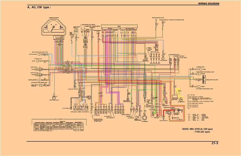
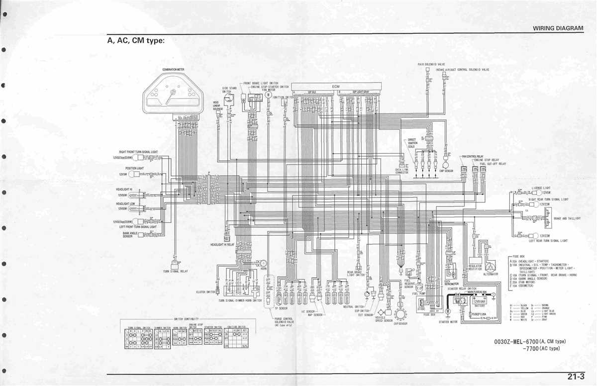
If you are a proud owner of a 2004 Honda CBR 600 F4i motorcycle, you know how important it is to have a good understanding of its wiring diagram. The wiring diagram is a detailed depiction of the electrical system of your bike, and it provides a clear and concise map of all the electrical connections and components. With this diagram, you will be able to troubleshoot any electrical issues that may arise and make any necessary repairs or modifications.
The 2004 Honda CBR 600 F4i wiring diagram includes information on the colors and functions of each wire, as well as the location of each component. This diagram will help you identify and understand the various electrical circuits, such as the ignition system, lighting system, fuel injection system, and more. It will also give you a better understanding of how these circuits are interconnected and how they work together to power your motorcycle.
Whether you are a seasoned mechanic or a DIY enthusiast, having access to the 2004 Honda CBR 600 F4i wiring diagram will prove to be invaluable. It will save you time and frustration by allowing you to quickly and easily diagnose and fix electrical problems. It will also give you the confidence to perform any necessary electrical modifications or upgrades on your bike.
In conclusion, the 2004 Honda CBR 600 F4i wiring diagram is a must-have tool for any owner of this iconic motorcycle. It provides a comprehensive guide to the electrical system, allowing you to troubleshoot and repair any issues that may arise. Whether you are a professional mechanic or a hobbyist, this wiring diagram will help you maintain and customize your bike to perfection.
Understanding the Wiring Diagram for a 2004 Honda CBR 600 F4i
When it comes to understanding the wiring diagram for a 2004 Honda CBR 600 F4i, it is essential to have a clear understanding of the different components and their connections. The wiring diagram represents the electrical system of the motorcycle, showing how each component is connected and how electrical current flows through the system.
In the wiring diagram, you will find various symbols and lines that represent different components and their connections. For example, lines with arrows indicate the direction of electrical current flow, while various symbols represent different parts such as the ignition switch, battery, lights, and sensors. By referring to the wiring diagram, you can easily identify these components and their connections.
The wiring diagram is divided into sections, each representing a specific part of the electrical system. These sections include the ignition system, lighting system, charging system, fuel system, and various sensors. Each section provides a detailed illustration of how the specific component is connected to the main electrical system and to other components within its section.
One important aspect of understanding the wiring diagram is understanding the color codes used. Different colors are used to represent different wires and their functions. For example, the color black usually represents the ground wire, while red represents power or the positive side of the electrical system. By being familiar with these color codes, you can easily trace and identify the wires in the wiring diagram.
By studying and understanding the wiring diagram for a 2004 Honda CBR 600 F4i, you can gain valuable knowledge about the electrical system of the motorcycle. This knowledge can be useful for troubleshooting electrical issues, making modifications, or simply understanding how the different components are connected. Whether you are a professional mechanic or a motorcycle enthusiast, having a good understanding of the wiring diagram can help you maintain and repair your Honda CBR 600 F4i more effectively.
Overview
The 2004 Honda CBR 600 F4i is a sport motorcycle that was manufactured by Honda from 2001 to 2006. It is known for its powerful engine, sleek design, and excellent performance on both the street and the track.
The wiring diagram is an essential tool for anyone who owns or works on a 2004 Honda CBR 600 F4i motorcycle. It provides a detailed illustration of the electrical system and wiring connections for various components, such as the ignition system, lights, and controls.
Key Features
- Powerful engine: The 2004 Honda CBR 600 F4i is equipped with a 599cc liquid-cooled inline four-cylinder engine, delivering impressive power and torque.
- Sleek design: With its aerodynamic fairings, sharp lines, and aggressive stance, the CBR 600 F4i has a visually appealing design that stands out on the road.
- Excellent performance: The combination of the powerful engine, lightweight frame, and advanced suspension system allows for exceptional performance and handling.
- Comfortable riding position: The CBR 600 F4i features a sporty, yet comfortable riding position, making it suitable for both short commutes and longer rides.
Whether you are a motorcycle enthusiast, a mechanic, or a DIY owner, having access to the wiring diagram of the 2004 Honda CBR 600 F4i is essential for troubleshooting electrical issues, installing aftermarket accessories, or performing any modifications. It provides a valuable resource for understanding the electrical system and ensuring proper connections for optimal performance and safety.
What is a wiring diagram?
A wiring diagram is a visual representation of the electrical connections and wiring in a system or device. It uses symbols and color codes to illustrate the different components and their interconnections. Wiring diagrams are commonly used in various industries, including automotive, construction, and electronics, to help technicians and engineers understand how electrical systems are organized and how to troubleshoot issues.
In the context of a 2004 Honda CBR 600 F4i motorcycle, a wiring diagram would provide a detailed illustration of the electrical wiring and connections specific to that model. This diagram would show all the components involved in the electrical system, such as the ignition switch, battery, lights, and sensors, as well as the wires that connect them.
A wiring diagram is essential for diagnosing electrical problems, planning modifications or upgrades, and understanding how different parts of the system are connected. It helps technicians identify the correct wires or components to test, repair, or replace. Without a wiring diagram, troubleshooting electrical issues would be much more challenging and time-consuming.
Wiring diagrams can vary in complexity and level of detail, depending on the specific application or system. They can be simple, showing only the basic connections and components, or more complex, highlighting every wire and connection in a detailed schematic diagram. Some wiring diagrams may also include additional information, such as wire colors, pin numbers, and circuit functions.
Overall, a wiring diagram is a valuable tool for anyone working with electrical systems. It provides a visual reference that helps to understand the wiring layout and connections, making it easier to identify and solve electrical problems efficiently. Whether you are a professional technician or a DIY enthusiast, having access to accurate wiring diagrams is essential for successfully working with electrical systems.
The Importance of a Wiring Diagram for a Motorcycle
When it comes to working on your motorcycle, having a wiring diagram is absolutely essential. It serves as a guide that shows the electrical connections and wiring configurations of your motorcycle’s various components. Without a wiring diagram, troubleshooting electrical problems or making modifications can be extremely difficult and time-consuming.
A wiring diagram provides a visual representation of the electrical system of a motorcycle, including the wires, connectors, and components. It allows you to trace the flow of electricity through the system, making it easier to identify any faulty connections or components that may be causing issues.
One of the main benefits of having a wiring diagram is that it allows you to understand how the electrical system of your motorcycle is organized. This can be particularly useful when it comes to adding new accessories or modifying the existing wiring. With a wiring diagram, you can easily identify the appropriate wires and connectors to tap into, ensuring that your modifications are done correctly and safely.
In addition to providing guidance for repairs and modifications, a wiring diagram can also be a valuable tool for preventative maintenance. By understanding the electrical system of your motorcycle, you can spot potential issues before they become major problems. Regularly inspecting and testing the wiring connections can help prevent electrical failures or malfunctions, which can ultimately save you time and money.
In conclusion, a wiring diagram is an essential tool for any motorcycle owner or technician. It provides a visual representation of the electrical system, making it easier to troubleshoot problems, make modifications, and perform preventative maintenance. Whether you are a professional mechanic or a DIY enthusiast, having a wiring diagram can greatly simplify your work and keep your motorcycle running smoothly.
The Main Components
The 2004 Honda CBR 600 F4i wiring diagram consists of several main components that play a crucial role in the functioning of the motorcycle’s electrical system. These components include the ignition switch, the engine stop switch, the starter button, the main power wire, the fuse box, and various wires and connectors.
The ignition switch is a key component that allows the rider to start and stop the engine. It is typically located on the right side of the handlebar and is used to control the electrical power flow to different parts of the motorcycle. The engine stop switch, on the other hand, is used to cut off the fuel supply and stop the engine in case of an emergency or when the motorcycle is parked.
The starter button is another important component that is typically located on the right side of the handlebar. When pressed, it sends a signal to the starter motor, which in turn cranks the engine and starts it. The main power wire is responsible for delivering electrical power from the battery to the different parts of the motorcycle’s electrical system.
The fuse box is an essential component that protects the electrical system from damage caused by an overload or short circuit. It contains fuses of different ratings that are designed to blow and break the circuit in case of an electrical fault. This helps prevent damage to the electrical components and wiring of the motorcycle.
In addition to these main components, the wiring diagram also shows various wires and connectors that connect the different electrical components of the motorcycle. These wires and connectors ensure the proper flow of electrical power and signals between the components, allowing them to work together seamlessly.
Engine Wiring
The engine wiring of a 2004 Honda CBR 600 F4i is a crucial component that connects various electrical components to the engine. It includes a network of wires, connectors, and sensors that enable communication and control between the engine and other systems in the motorcycle.
The engine wiring diagram provides a visual representation of the electrical connections and circuits of the motorcycle’s engine. It shows the routing of wires, the locations of connectors, and the functions of various components. This diagram is essential for troubleshooting electrical issues, performing repairs, and understanding the overall electrical system of the vehicle.
In the engine wiring of the Honda CBR 600 F4i, there are several key components and systems that are connected. These include the ignition system, fuel injection system, charging system, starter motor, and various sensors such as the throttle position sensor and engine temperature sensor.
- The ignition system includes the ignition coil, spark plugs, and the ignition control module. It is responsible for generating the spark that ignites the air-fuel mixture in the engine cylinders.
- The fuel injection system consists of the fuel injectors, fuel pump, and electronic control unit (ECU). It controls the amount of fuel injected into the engine cylinders based on various inputs such as throttle position and engine load.
- The charging system includes the generator, rectifier, and battery. It is responsible for generating electrical power and maintaining the battery’s charge.
- The starter motor is connected to the battery and is responsible for cranking the engine during startup.
Overall, the engine wiring of the 2004 Honda CBR 600 F4i plays a vital role in ensuring the proper functioning of the engine and its various systems. It is important to have a thorough understanding of the engine wiring diagram and to properly maintain and repair any issues that may arise.
Chassis wiring
When it comes to the chassis wiring of the 2004 Honda CBR 600 F4i, there are several important components and connections that make up this system. These components are responsible for transmitting electrical signals and power throughout the motorcycle, ensuring the proper functioning of various systems and features.
One crucial element of the chassis wiring is the main wiring harness, which serves as the backbone of the system. This harness consists of numerous wires that connect various parts of the motorcycle, such as the ignition system, lighting system, and instrument cluster. The main wiring harness is routed through the frame of the bike, ensuring optimal protection and organization of the wiring system.
Another important component of the chassis wiring is the fuse box. The fuse box contains several fuses, each of which protects a specific electrical circuit from damage caused by excessive current flow. By preventing overloads, the fuse box helps to maintain the integrity of the electrical system and protect sensitive components from damage.
The chassis wiring also includes connections for the various lights on the motorcycle, such as the headlights, taillights, and turn signals. These connections ensure that the lights operate correctly and provide the necessary visibility and safety for the rider.
In addition to these components, the chassis wiring includes various switches and relays that control different functions, such as the ignition, starter motor, and horn. These switches and relays allow the rider to easily control and activate different systems and features on the motorcycle.
Overall, the chassis wiring of the 2004 Honda CBR 600 F4i is a complex system that plays a vital role in the overall functionality and safety of the motorcycle. It is important to follow the wiring diagram and ensure proper installation and maintenance of the wiring components to ensure optimal performance and reliability.
Electrical components
Honda CBR 600 F4i (2004) is equipped with a variety of electrical components that are essential for the proper functioning of the motorcycle’s electrical system. These components include:
- Battery: The battery provides the initial power supply for the motorcycle’s electrical system. It stores energy from the charging system and supplies it to various electrical components.
- Charging system: The charging system consists of a stator, rotor, rectifier, and regulator. It is responsible for generating electricity and charging the battery while the motorcycle is running.
- Ignition system: The ignition system is responsible for igniting the air-fuel mixture in the engine’s cylinders. It includes components such as the ignition coil, spark plug, and ignition switch.
- Starter motor: The starter motor is an electric motor that is used to start the engine. It is powered by the battery and engages with the engine’s flywheel to start the combustion process.
- Lights: The lights on the Honda CBR 600 F4i include headlights, turn signals, brake lights, and taillights. These lights are essential for providing visibility and safety while riding.
- Wiring harness: The wiring harness is a bundle of wires that connects all the electrical components of the motorcycle. It allows for the transfer of electrical signals between components and ensures proper functionality.
Overall, the electrical components of the Honda CBR 600 F4i (2004) play a crucial role in its operation. They provide power for the engine ignition, lighting, and other electrical systems, ensuring that the motorcycle functions properly and safely. Regular maintenance and inspection of these components are essential for the longevity and reliability of the motorcycle’s electrical system.
Q&A:
What are electrical components?
Electrical components are devices that can manipulate electric current in different ways in order to perform a specific function in an electrical circuit.
What are some common types of electrical components?
Some common types of electrical components include resistors, capacitors, inductors, diodes, transistors, and integrated circuits.
What is a resistor?
A resistor is an electrical component that limits the flow of electric current in a circuit. It is used to control the amount of current or to create a voltage drop.
What is a capacitor?
A capacitor is an electrical component that can store and release electric charge. It is commonly used in circuitry to stabilize voltage, filter out noise, or store energy.
What is a transistor?
A transistor is a semiconductor device that can amplify or switch electronic signals and electrical power. It is one of the fundamental building blocks of modern electronics.
What is an electrical component?
An electrical component is a device that can carry electrical signals or currents within an electrical circuit.
What are some common electrical components?
Some common electrical components include resistors, capacitors, diodes, transistors, inductors, and integrated circuits.