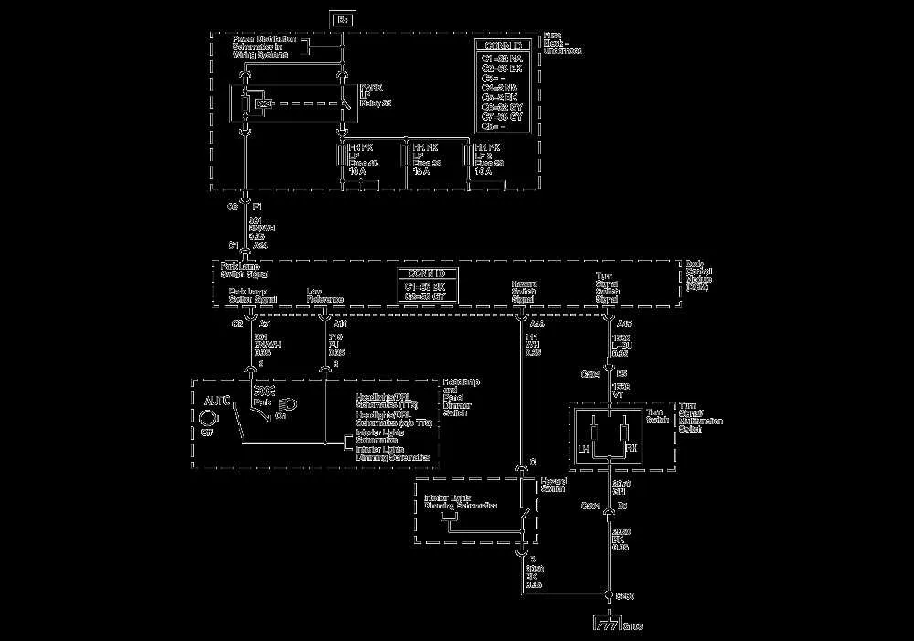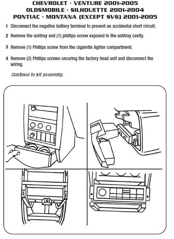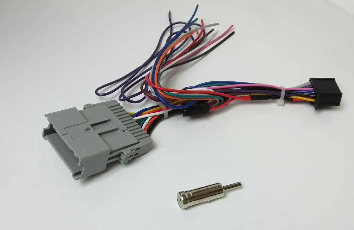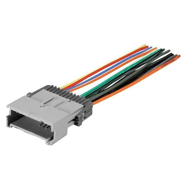
If you need to connect or troubleshoot your vehicle’s entertainment system, refer directly to the specific connection layout for your model’s head unit. Knowing the exact pinout of the connectors is crucial for ensuring proper installation and function. The connectors typically consist of power, ground, speaker, and antenna pins, all of which must be correctly identified to avoid wiring errors that could damage the system.
Start with the power supply wiring, which includes the constant 12V and switched 12V lines. The constant 12V should be connected to a source that is always on, even when the vehicle is off. This is necessary to maintain memory functions like station presets and clock settings. The switched 12V line, on the other hand, powers up the unit only when the ignition is on, preventing battery drain when the vehicle is off.
Next, check the speaker wiring configuration. Most vehicles use a standard color-coding scheme for speaker wires. Typically, a positive wire will be identified by a specific color and a corresponding negative wire will have a distinct color or stripe. Ensure these wires are correctly matched with the corresponding speakers to maintain proper sound output and avoid potential damage to both the system and the speakers.
Lastly, consider antenna connections, especially if you’re dealing with a system that uses an external antenna or has a built-in amplifier. The antenna wire connects to the unit, enabling the reception of radio signals. It’s essential to ensure the antenna is properly seated and that no corrosion or damage has occurred at the connection point.
Wiring Connections for the 2005 Truck Audio System

Ensure that you identify the key power, ground, and speaker wire connections correctly to avoid damaging the system. The power wire is typically red, while the ground wire is black. The speaker wires, often color-coded, should match with the speaker terminals in the vehicle’s interior. Make sure to verify the color codes for each specific model for accurate connection.
If you are replacing the unit, make sure to disconnect the negative terminal from the battery before starting the installation. This will prevent any electrical issues or short circuits during the process.
For audio system installation, connect the ignition wire (usually yellow) to the unit’s power, ensuring it powers up only when the ignition is on. For speakers, ensure proper polarity, where the positive wire connects to the positive terminal of the speaker to avoid sound distortion.
Use a multimeter to verify voltage on the power and ground wires before connecting them to ensure proper operation. If you experience issues with the system not powering on, check for any blown fuses in the fuse panel or the unit itself.
Identifying the Key Wires in the 2005 Chevy Colorado Radio Wiring Diagram

When working with the electrical connections for the entertainment system, focus on the primary wires responsible for power, sound, and control functions. Here are the most critical elements to identify:
- Power Wire (12V Constant): Typically, this wire provides constant power to the system, ensuring settings are saved even when the vehicle is off. It is usually color-coded yellow.
- Switched Power Wire: This wire is activated when the ignition is on, delivering power to the head unit. It is often marked with a red color.
- Ground Wire: A secure connection to the vehicle’s chassis is necessary for proper operation. Typically, this wire is black.
- Speaker Wires: These are essential for transmitting audio signals to the speakers. Each speaker has a positive and negative wire, with colors like green/green-black, purple/purple-black, and more.
- Illumination Wire: Responsible for dimming the system’s display when headlights are on. This wire is often orange or orange-white.
- Amplifier Turn-On Wire: For systems that include an external amplifier, this wire activates the amplifier. Typically blue, it should be connected properly to ensure sound amplification.
These connections are the most critical when replacing or installing the entertainment system. Make sure to match the colors and functions accurately for optimal performance.
Step-by-Step Guide for Installing a New Stereo System in a 2005 Pickup Truck
Start by disconnecting the vehicle’s battery to ensure safety during installation. This will prevent any short circuits or damage to the electrical components. After that, remove the existing head unit by unscrewing any visible mounting bolts. Use a trim removal tool to gently pry off the dashboard panels around the unit without damaging them.
Next, disconnect the wiring harnesses and antenna cable from the back of the old unit. If your new system doesn’t come with an adapter, you’ll need to purchase a harness that matches your vehicle’s electrical connections. Carefully match the wires: the power supply, ground, and speakers must be correctly aligned to avoid damage.
Before inserting the new head unit, test the connections by briefly reconnecting the battery to ensure all the wires are in the right place. This will help you avoid troubleshooting after the installation is complete.
Once the connections are verified, connect the new unit’s wiring to the matching harness. Install any necessary adapters for additional features such as Bluetooth or aux inputs. Slide the new system into the mounting bracket, ensuring it fits snugly in place. Tighten any screws or bolts to secure it.
Finally, reattach the dashboard panels and connect the vehicle’s battery. Turn on the system and test all functions, including sound output, Bluetooth connectivity, and auxiliary ports. If all features are working as expected, the installation is complete.
Troubleshooting Common Audio System Wiring Problems

When experiencing issues with the audio system, the first step is to check the power connections. Ensure the positive power wire is securely connected to the battery terminal and that the ground wire is properly attached to a metal surface in the vehicle. A loose ground can lead to a poor connection and malfunction.
If the system fails to turn on, inspect the fuse linked to the electrical components. Replace any blown fuses with the correct amperage, which is usually indicated on the fuse box cover or vehicle manual.
In cases where only some speakers produce sound, check the speaker wires for any fraying or breaks. An exposed wire might cause intermittent or no sound output. Tighten any loose connections and replace damaged wires.
For systems with poor sound quality or distortion, verify the signal cable connections. A damaged or improperly seated wire can introduce interference. Ensure the connectors are free from corrosion and that the cable is intact.
If the issue persists after checking these components, inspect the amplifier connections. The amplifier may be disconnected or damaged. Confirm that the amplifier power supply and ground connections are intact and that the speaker wires are properly routed to avoid short circuits.
Finally, for intermittent problems, check the vehicle’s multimeter readings to assess voltage levels across the system. Consistent voltage fluctuations could indicate an issue with the alternator or the power delivery system, requiring further diagnosis.