If you’re planning to install a low-voltage lighting system, it’s essential to have a clear understanding of how to properly connect the components for optimal performance and safety. Proper configuration ensures both efficiency and durability of the setup.
The first step is ensuring you have a power source that matches the voltage requirements of your system. Use a transformer that can step down the current to the appropriate level for your installation. This helps avoid potential damage to the system.
When connecting the units, ensure you use high-quality conductors that are rated for low-voltage applications. Properly selecting and measuring the wires will prevent issues like voltage drops or overheating. Pay attention to the polarity of connections as incorrect wiring can lead to malfunction.
Be mindful of the maximum load the transformer can handle. Exceeding this limit will result in inefficient operation or complete failure of the circuit. Also, consider using appropriate fuses to protect the components and prevent short circuits.
Ensure that each component is securely mounted, with connections properly insulated to avoid contact with moisture or other damaging elements. If you’re unsure, consult with a professional to ensure your setup is safe and effective.
Electrical Connection Setup for Low-Voltage Fixtures
For efficient and safe installation of low-voltage fixtures, follow these steps:
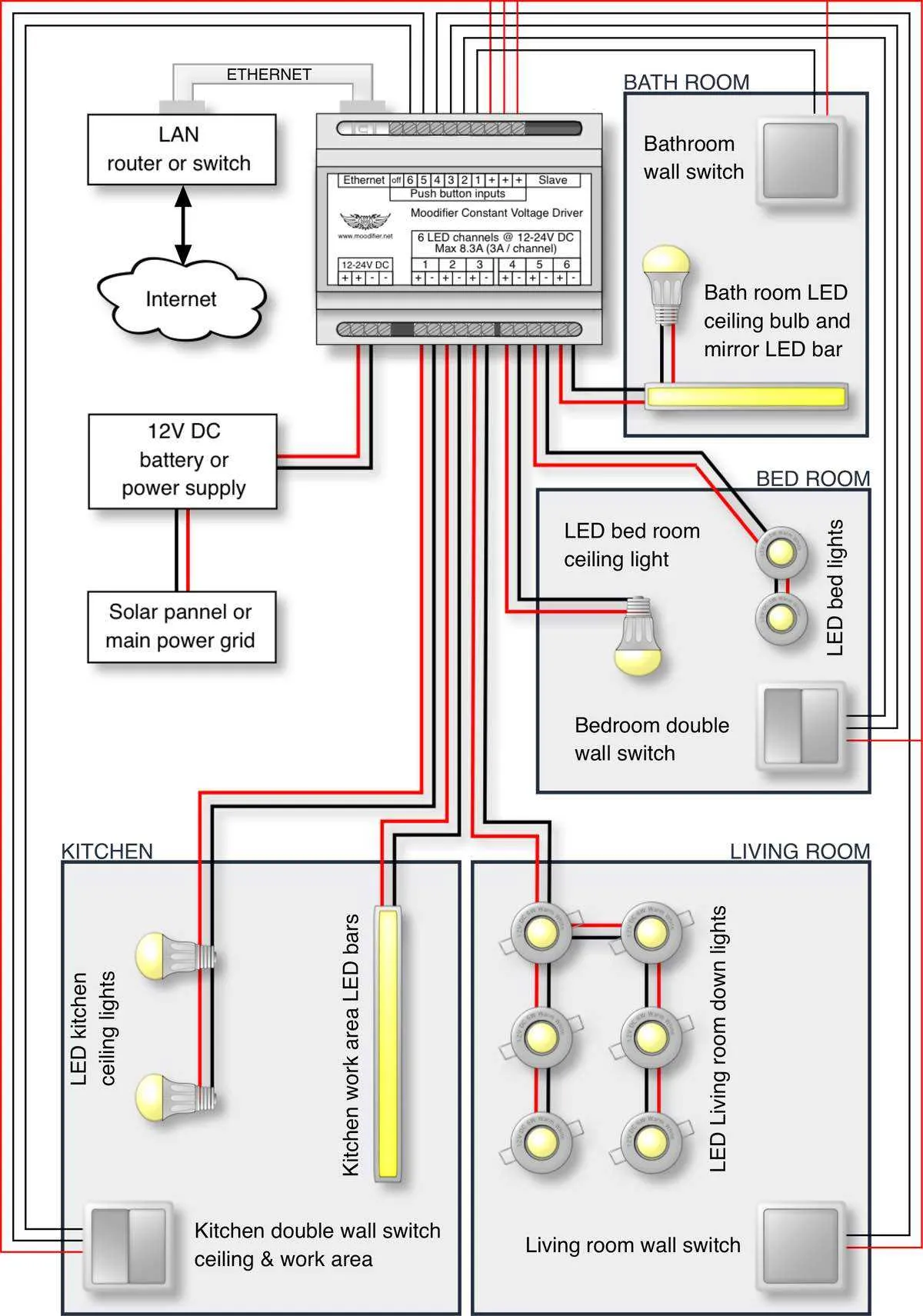
- Power Source Connection: Begin by connecting the power supply to a suitable transformer that converts the household voltage to the required level for the fixtures.
- Proper Gauge of Wire: Use wires of appropriate thickness to handle the current demand. For most low-voltage setups, 18-20 AWG is ideal, but check the manufacturer’s recommendations for your specific fixtures.
- Polarization Check: Ensure the polarity of the connection is correct. Typically, the positive terminal should be connected to the “+” on your fixtures, while the negative connects to the “-“.
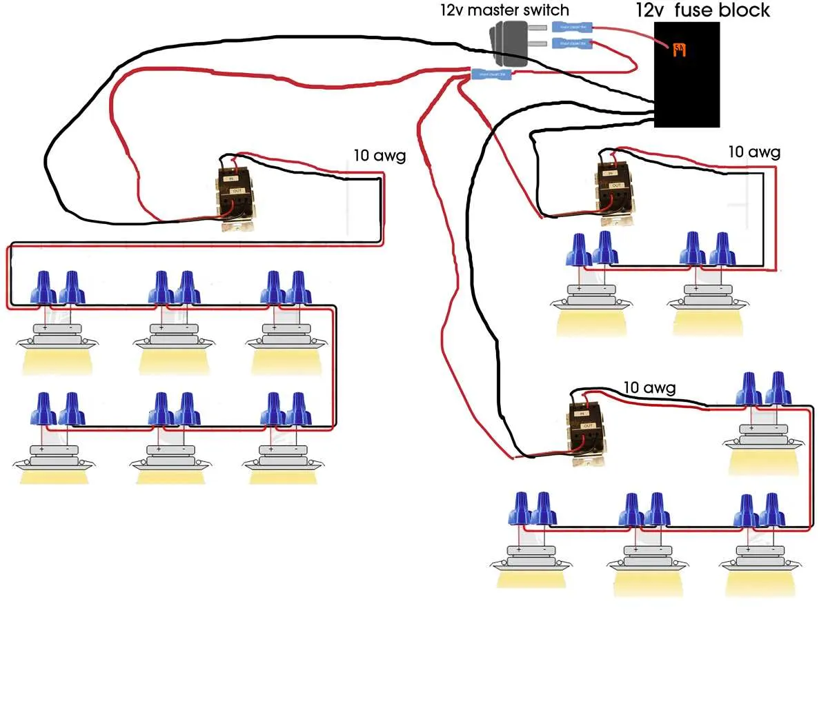
- Series vs Parallel: Decide whether to wire your components in series or parallel. Series will reduce the voltage across each fixture, while parallel ensures each one gets the full voltage from the transformer.
- Connection to Fixtures: Use appropriate connectors or terminals to securely attach the wires to the fixtures, ensuring no loose connections that can lead to short circuits or faulty operation.
When connecting multiple units, always check the total wattage of all fixtures combined. Ensure that your transformer and wires can support the total load. If in doubt, overestimate to prevent issues during operation.
- Always test the setup before finalizing the installation.
- Use weatherproof connectors if the setup is outdoors or exposed to moisture.
- Ensure that the transformer is rated correctly for the voltage and wattage of your setup.
Proper insulation of wires and a secure installation will ensure long-lasting and safe operation of your low-voltage system.
How to Connect Strips to a Power Supply

Start by ensuring the power source voltage matches the requirements of your strip. The current rating should be sufficient to support the total power consumption of the strip. Typically, strips require a regulated output, so choose a reliable adapter that matches the total wattage needed for the project.
First, identify the polarity of the power connector. Most strips come with clear indicators for the positive (+) and negative (-) terminals. Connect the positive terminal of the adapter to the positive input of the strip and the negative terminal to the corresponding negative input. Use proper connectors or solder the wires securely to avoid poor contacts.
To prevent overheating, select wires with appropriate gauge size. If the strip is long or you plan to run multiple strips, use thicker cables to handle the increased current without excessive voltage drop.
If your strip is long, consider adding a connector at the end to allow for an easy extension. Ensure that the connections are tight, and if soldering, use heat shrink tubing to protect against short circuits. In some setups, you may need to add a fuse in line with the positive lead to protect the circuit from power surges or faults.
Once all connections are made, double-check the integrity of each joint, ensuring there’s no exposed wire that could lead to a short. Finally, power up the setup, and ensure the connection is stable before use.
Understanding the Role of Resistors in Low-Voltage Circuit Design
Resistors are essential for controlling the current flow and preventing damage to sensitive components in low-voltage circuits. When designing such systems, it’s crucial to choose the right resistor value to ensure proper function and longevity of your components.
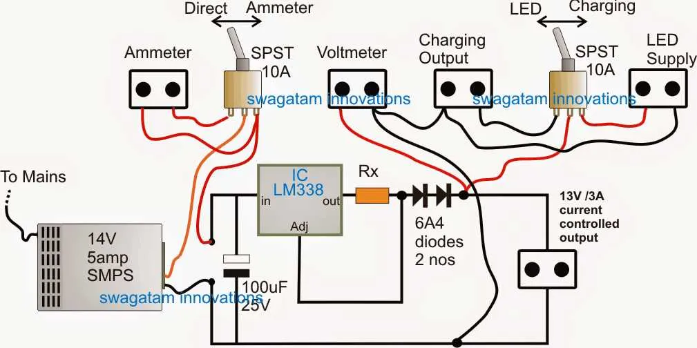
Without a resistor, the current can exceed the safe operating limit, leading to overheating or failure. Typically, a series resistor is used to limit the current, balancing the voltage supplied to the components. This is especially important for devices that are rated for specific currents.
The resistor value is calculated based on the required current and the voltage drop needed across the resistor. Using Ohm’s Law (V = IR), you can calculate the required resistance to ensure the right current flows through your system. For example, if the operating current is 20mA and the voltage across the resistor needs to be 10V, the required resistance would be 500 ohms (R = V/I).
Power rating of the resistor is another important factor. It ensures the resistor can dissipate the heat generated by the current flowing through it. For safety, the resistor’s power rating should always be higher than the actual power dissipation in the circuit.
In circuits where multiple components are connected in parallel or series, careful calculation of individual resistors ensures that each part functions optimally without overloading or wasting energy.
Key Takeaway: Always match the correct resistance and power rating to prevent failure and maintain performance in your system.
Connecting Multiple LEDs in Series and Parallel Configurations

When connecting multiple low-voltage diodes, it’s important to choose the right method: series or parallel, depending on the intended application. In series, the positive terminal of one unit connects to the negative of the next, creating a chain. This increases the total voltage required but keeps the current the same as a single diode. The total voltage is the sum of individual voltages. Ensure the power source can handle the combined voltage load.
For parallel setups, each unit connects directly to the power source with matching positive and negative terminals. This configuration maintains the same voltage across all units, while the current adds up. It’s crucial to ensure that the power supply provides sufficient current to power all units simultaneously. Each diode should also be of similar specification to avoid uneven power distribution.
In either configuration, use resistors if necessary to regulate current, particularly in series arrangements, to prevent excessive current flow through individual units. Also, verify the capacity of the power supply to avoid overloading. When connecting multiple diodes in either way, ensure solid connections and proper insulation to prevent shorts or other issues.