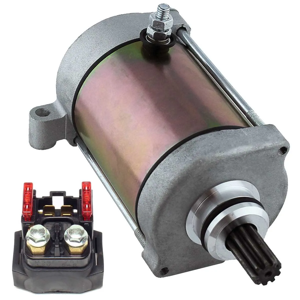
To ensure reliable operation of the four-wheeler’s power distribution, follow the precise schematic for its electromagnetic switch connections. Proper identification of the coil terminals and contact points will prevent common electrical faults such as intermittent power loss or starter failure.
Locate the main control switch terminals on the vehicle’s circuit board to verify continuity before replacing any components. Testing the relay coil resistance within the specified range confirms functional integrity, typically around 70–100 ohms.
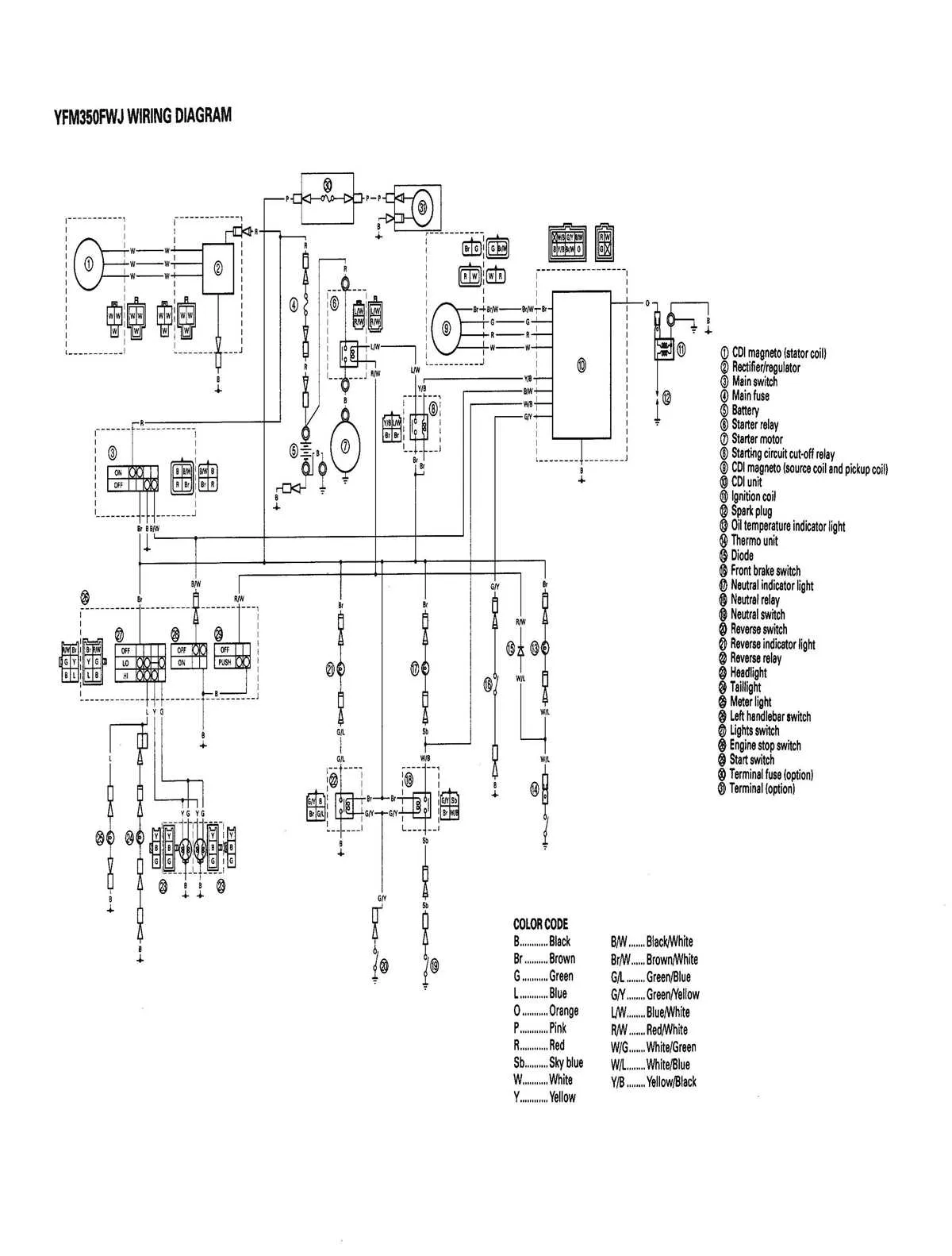
Pay attention to the connection paths from the battery to the ignition system and starter motor. Any deviation or corrosion in these lines can cause malfunctioning. Use the referenced wiring map to trace each wire color code and terminal designation for accurate troubleshooting and repairs.
Electrical Relay Wiring for the 2005 Yamaha Rhino 660

For troubleshooting or replacement of the electrical switch component in this ATV model, refer to the following layout and connection points. Accurate understanding of the wiring harness and switch terminals prevents common faults and ensures proper operation.
- Power Input Terminal: Connects directly to the battery positive, supplying voltage to the switching device.
- Ground Terminal: Provides circuit grounding, essential for completing the electrical flow.
- Control Coil Input: Receives a signal from the ignition or control module to activate the switch mechanism.
- Load Output Terminal: Sends power to the starter motor or other controlled devices when energized.
Key wiring colors to identify:
- Red/Black: Battery feed line
- Green: Ground line
- Blue/White: Control signal wire
- Yellow: Output to starter or accessory
- Verify continuity between the input and output terminals using a multimeter before installation.
- Check the coil resistance to ensure it falls within manufacturer specifications (usually 50-100 ohms).
- Secure all connectors firmly to prevent voltage drops or intermittent failures.
- Use dielectric grease on terminals to reduce corrosion risk.
Following this wiring layout and terminal identification will assist in quick diagnostics and safe replacements of the switch component responsible for power routing within this off-road vehicle’s electrical system.
Locating and Identifying the Main Electrical Switches on the ATV

Begin by accessing the central fuse box beneath the driver’s seat area. The primary control units are typically secured within this compartment for protection against elements and vibrations. Look for a compact rectangular module with multiple terminals and a distinct plastic casing, usually black or dark gray.
Key identifiers include part numbers molded into the housing and the presence of heavy-gauge wiring connected to the battery and ignition system. These switches manage the main power flow to essential engine components.
To pinpoint the exact unit, trace the thick red cable originating from the battery positive terminal; it leads directly to the main power controller. Additionally, smaller wires branching from this unit connect to the starter motor and ignition coil, confirming its function.
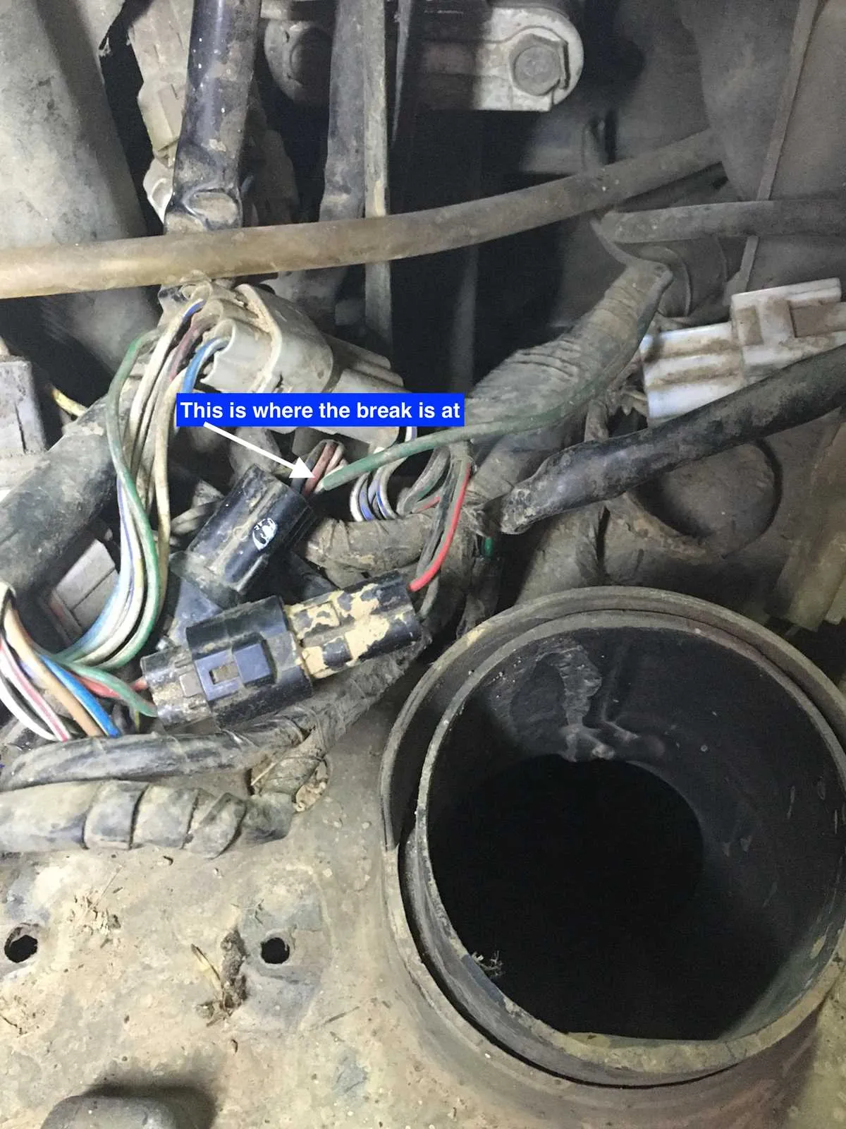
Inspect the connectors for corrosion or looseness, which can cause intermittent power loss or failure to start. Ensuring secure attachment and clean contacts improves reliability.
For servicing, the control modules are often clipped or screwed into the frame near the battery tray. Removing any protective panels or side covers may be necessary to gain full access.
Step-by-Step Guide to Reading the Electrical Control Schematic for the Off-Road Utility Vehicle

Locate the power source and ground connections first. Identify the main battery feed line and the chassis ground to understand the flow of current. This establishes the foundation for tracing circuits.
Identify the coil and switch terminals. The electromagnetic switch coil will have two terminals: one connected to the control circuit and the other to ground. Recognizing these points helps differentiate control and power sides.
Trace the input trigger wire. This wire usually originates from a control switch or sensor and activates the switching mechanism. Follow its path to verify proper input signals.
Follow the output load circuit. After the switching contacts, track the power line leading to the component being controlled, such as the starter motor or lights. Confirm connections and wire colors to avoid confusion.
Check the schematic symbols. Familiarize yourself with the standardized icons representing coils, contacts, and terminals. Understanding these symbols aids in quick interpretation without guesswork.
Use pin numbering as reference. Connector pins and terminal numbers are essential for matching physical components with the schematic, ensuring accurate wiring and troubleshooting.
Verify fuse and relay positions. Locate protection devices within the circuit to confirm continuity and safety measures are in place before proceeding with testing or repairs.
Cross-reference with component layout. Compare the electrical schematic with the physical arrangement of parts to streamline diagnostics and avoid errors during maintenance.
Following these steps systematically improves efficiency when working with complex electrical control schematics for off-road vehicles.
Troubleshooting Common Electrical Issues Using the Relay Diagram
Start by testing the starter control circuit: if the engine doesn’t crank, inspect the ignition switch output using a multimeter. Confirm voltage reaches the actuator terminal when the key is turned to the “start” position.
Next, verify the continuity between fuse box and contact block: no voltage may indicate a broken wire or corroded connector. Clean terminals and recheck resistance along the harness route.
Check the fuel pump trigger path: if there’s no priming sound, trace the low-current activation circuit from ECU to the switching node. Faulty grounding or a short could prevent proper engagement.
Evaluate lighting malfunctions: inconsistent headlights or brake lamps usually point to a faulty load-switching element. Swap with a known-good module of the same rating to isolate the issue.
Inspect fan control sequences: if the cooling fan doesn’t engage at high temperatures, confirm the thermal sensor input reaches the control module, and that output voltage appears on the high-power terminal when needed.
Confirm accessory power issues: for dead winches or auxiliary lights, ensure power is present at the control socket and test for internal continuity using the schematic to identify specific pathways.