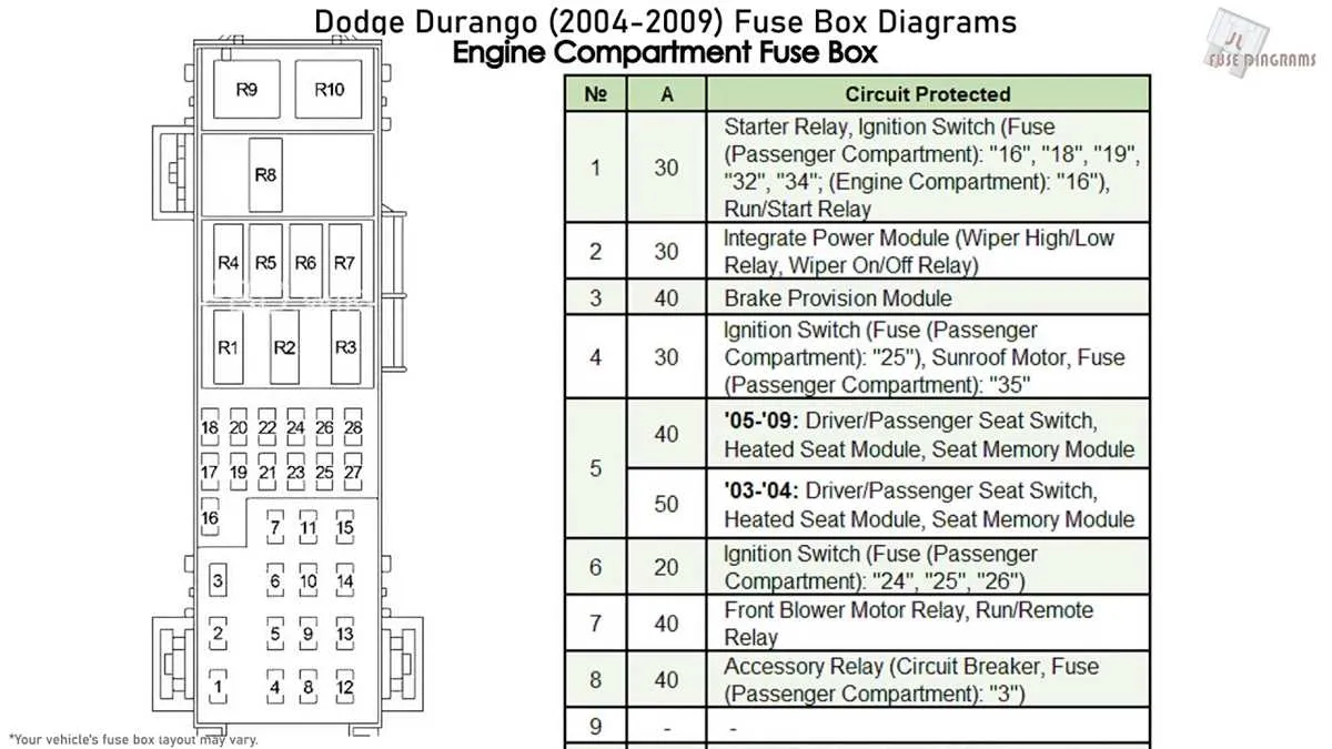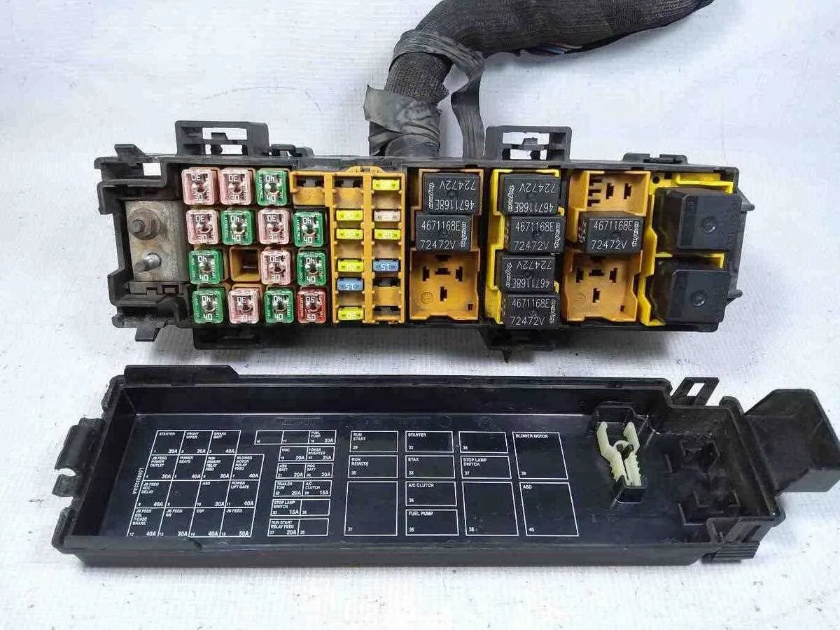
For optimal functionality, it is crucial to understand the layout of the electrical components in your vehicle. Begin by consulting the detailed wiring chart, which provides the location and function of each electrical module. This will help you identify which relays and circuits are responsible for various vehicle systems, such as lighting, air conditioning, and audio systems.
Ensure you check the specific connections for critical components. For instance, the primary connections that manage the vehicle’s start-up process or those powering safety features like airbags and braking systems should be regularly inspected. These areas are typically marked with color codes or numbered sections to guide you effectively.
By following this structured reference, you can easily locate any faulty part and replace or repair it without unnecessary confusion. Having this map on hand will save you significant time when troubleshooting or making adjustments to your vehicle’s electrical layout.
Regular checks of these systems are recommended to avoid costly repairs in the future. Proper maintenance of each circuit ensures that the vehicle’s electrical system remains reliable over time. Make sure to cross-check all connections and fuses after any work is done to prevent malfunctions.
Finally, having access to a clear layout of the electrical architecture allows for greater accuracy when performing installations or modifications. For instance, if you are adding aftermarket accessories or making electrical upgrades, knowing the exact placement and functions of these components will help you integrate them seamlessly into the existing system.
Electrical System Layout for the 2006 Vehicle Model
For troubleshooting or replacing components, refer to the central power distribution system located in the engine bay. The primary unit, which controls multiple electrical functions, is located near the driver’s side. Inside, it houses fuses for critical circuits such as headlights, ignition, and air conditioning.
Additional relays can be found in this assembly, each corresponding to key elements like the fuel system, windshield wipers, and interior lighting. Ensure that the relays are securely seated and test them using a multimeter if any function is malfunctioning. Some components, including the horn and ABS system, are linked to separate circuits, often housed in a secondary compartment near the dashboard.
If you need to replace a specific fuse, always verify the correct amperage. Using a fuse with an incorrect rating can result in wiring damage or complete circuit failure. Check the vehicle’s manual for the exact specifications of each circuit and location to ensure proper replacement.
For issues not related to individual fuses, consult the circuit diagram for a more detailed understanding of the wiring paths. This will help pinpoint faulty connections or short circuits that could be the source of your electrical problems.
Locating the Electrical Panel in a 2006 Dodge Vehicle

For quick access to the electrical components, locate the panel under the dashboard on the driver’s side. It is typically found to the left, near the lower corner of the footwell. You may need to remove a small cover to reveal the compartment. In addition, there is another essential panel positioned within the engine compartment. Open the hood and look towards the rear, near the driver’s side of the engine bay. Both locations house critical fuses and relays, so ensure you’re familiar with these areas for maintenance or troubleshooting purposes.
Identifying and Understanding Fuse Assignments in the Diagram
Locate the specific components or circuits by cross-referencing the numbering system on the panel with the related electrical functions. The numbers next to each terminal indicate the specific fuse’s position, simplifying troubleshooting. For clarity, always begin with the main power sources, followed by secondary circuits like lighting, air conditioning, or the ignition system. Check the amperage ratings indicated near each terminal to ensure they correspond to the right component requirements. These ratings are essential for understanding the amount of current the component can handle without risk of damage or failure.
Ensure that any identified blown elements are replaced with fuses of matching amperage to avoid overloading. The correct fuse assignment prevents electrical malfunctions, improving vehicle performance. When uncertain about the function, verify the connection with the vehicle’s manual or a service guide for confirmation of each slot’s role. For components requiring specific connections, such as ECU or powertrain elements, refer to detailed sections in the document for proper association.
In cases where electrical troubleshooting is necessary, use a multimeter to test the continuity of each connection. This ensures no faulty circuits are affecting the vehicle’s systems. Additionally, pay attention to any special instructions or warnings related to specific components, which may require more precise handling or specialized replacement parts.
How to Replace a Blown Fuse Using the Diagram
Start by identifying the location of the faulty component based on the layout provided. This layout will show the exact spot of each element, which helps quickly locate the problematic one.
- Turn off the vehicle to avoid any electrical accidents.
- Find the specific relay or circuit labeled in the schematic.
- Use a fuse puller or a pair of insulated pliers to remove the malfunctioning unit from its slot.
- Check the component for any visible damage like a broken filament or burn marks.
- Choose a replacement that matches the exact amperage and voltage rating as indicated in the schematic.
- Insert the new unit firmly into the slot, ensuring it is well seated and secure.
- Turn the vehicle back on to test the new component. If it works correctly, the issue is resolved.
Always double-check the schematic before making any replacements to ensure you are using the correct part for each circuit.