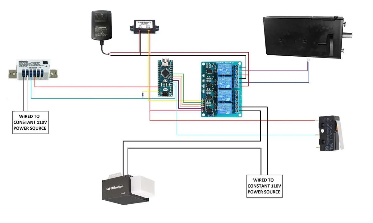
For proper setup of an automatic entrance mechanism, it’s critical to follow specific electrical guidelines. Ensure that all components, including motors, sensors, and control panels, are correctly connected. Mistakes in these connections can lead to malfunctions or safety hazards. Start by identifying the power supply requirements, which typically involve a 110V or 220V circuit, depending on the system type.
Next, connect the motor to the power line, ensuring that the wire gauge matches the specifications provided in the system manual. Incorrect wire sizing can result in overheating or failure to operate. Use a voltage tester to check that the correct voltage is being supplied to the motor before proceeding with other connections.
When linking sensors, always refer to their placement requirements for accurate operation. These sensors help detect obstacles and prevent accidents, so proper installation is paramount. Ensure the connections for safety sensors are securely tightened, as loose connections can disrupt the sensor signals.
Finally, double-check all connections before powering the system on. Conduct a test run to confirm the system functions as expected. If any issues arise, consult the manufacturer’s troubleshooting guide or consider seeking professional assistance to avoid further damage to the components.
Understanding Electrical Connections for Automated Openers

For a seamless setup of your automated entry system, focus on connecting the control board, sensor, and motor unit properly. First, ensure the power supply is cut off to avoid any electrical hazard. Connect the control unit to the motor’s terminals, confirming polarity is correct to prevent malfunction. Use solid copper wiring for all connections to minimize resistance and ensure reliable performance.
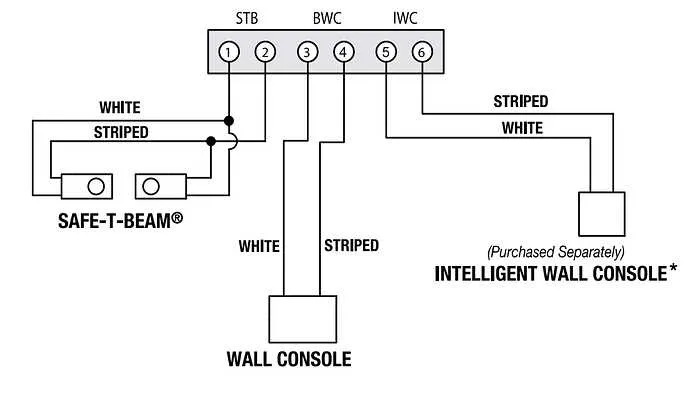
Connect the safety sensors on each side of the system, ensuring they are aligned properly. These sensors should be wired in parallel to the opener’s control unit for optimal functionality. Be sure the sensor wires are properly insulated and not subject to wear or abrasion. When running wires to the control unit, keep them as short as possible to avoid signal degradation.
If you are incorporating remote controls or a smart system, wire the receiver module directly to the opener’s motor unit. Ensure the signal connection is strong, using the proper shielding and grounding techniques. Check the receiver’s antenna placement for the best communication range.
Verify all connections using a multimeter to ensure voltage is stable at each point, particularly at the motor terminals and the control board. After confirming the integrity of your setup, restore power and test the system for smooth operation. Always follow manufacturer instructions specific to your model, as wiring configurations can vary significantly between brands and systems.
How to Connect a Motor for an Automatic Entry System

Start by turning off the power supply to the motor to avoid any electrical hazards. Use a voltage tester to confirm the absence of electricity at the circuit.
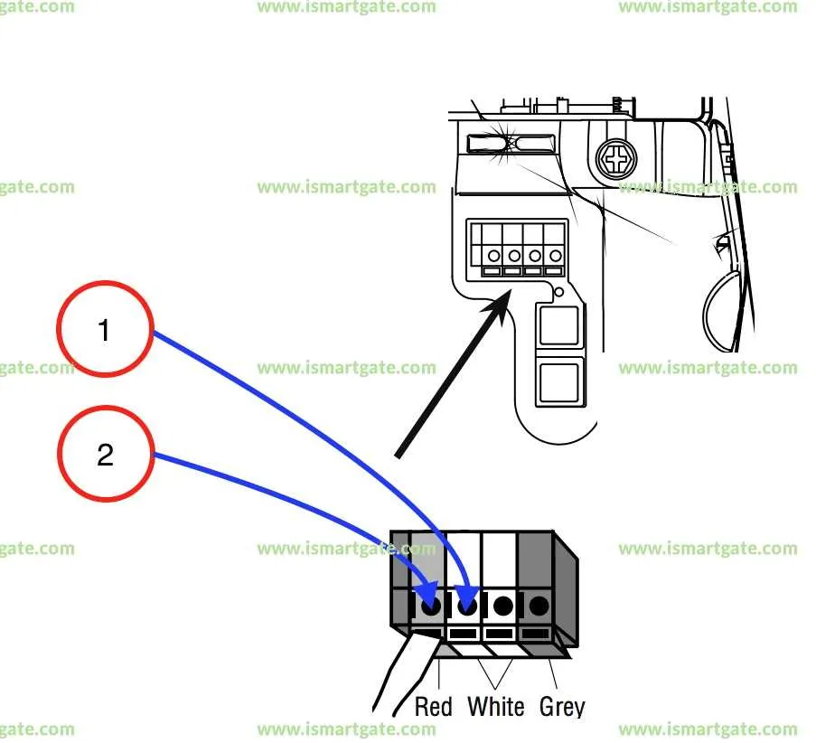
Locate the motor’s terminal block and identify the input terminals. Typically, you’ll have three wires: neutral, live, and ground. Attach the neutral wire (usually white) to the terminal marked “N” or “neutral,” and the live wire (usually black or red) to the terminal labeled “L” or “live.”
The ground wire (green or bare) should be securely connected to the ground terminal. Ensure that all connections are tight to prevent loose contacts that may lead to malfunction.
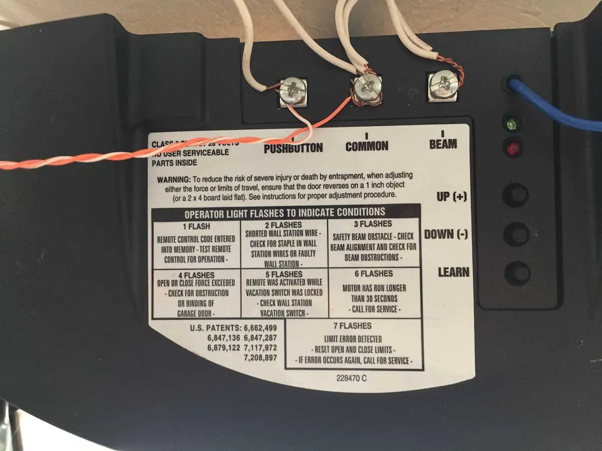
Next, connect the control wiring to the motor. If you are using a wall switch or remote control, follow the manufacturer’s instructions for wiring the switch to the designated control terminals on the motor.
For systems that include sensors, wire them to the terminals designed for safety features. These often include terminals marked “safety” or “sensor.” Ensure the sensor wiring is properly routed and shielded from external interference.
Once the system is wired, check for any exposed wires that could cause shorts. Double-check all connections and ensure that the control system is correctly paired with the motor. When satisfied, restore power to the unit and test the system to confirm proper functionality.
Wiring the Limit Switch and Safety Sensors in Overhead Doors

Start by connecting the limit switch to the opener’s control board. The limit switch has two terminals: one for the common (C) and the other for the Normally Open (NO) connection. Wire the C terminal to the control board’s common terminal, and the NO terminal to the activation terminal. This setup ensures the opener halts at the correct positions during the up and down cycles.
For the safety sensors, run wires from the control panel to the sensor terminals. Typically, the sensors use a two-wire connection, with one wire to the positive terminal and the other to the negative terminal. Make sure the sensors are aligned properly, as misalignment can cause them not to function, leading to safety issues. Ensure proper insulation and secure connections to avoid interference with signal transmission.
Test the functionality by manually moving the mechanism and observing whether the limit switch engages correctly and the sensors react to obstructions. Ensure the opener’s control system recognizes both the limit switch’s position and the sensor’s state before sealing the setup. Check for any loose connections or damage to the wires before testing the system’s operation to ensure safe, reliable function.
Common Electrical Errors and Troubleshooting Tips for Overhead Openers
Ensure the power supply is properly connected and functional. Check if the circuit breaker is tripped or the fuse is blown. If the opener isn’t receiving power, reset the breaker or replace the fuse.
- Incorrectly Wired Limit Switch: The limit switch controls the travel of the mechanism. If it is wired incorrectly, the system may not fully close or open. Verify the switch is set to the correct position, ensuring it aligns with the opener’s travel limits.
- Misaligned Safety Sensors: These sensors detect objects in the path of the opener. If misaligned, the opener may not respond or reverse prematurely. Clean the sensors and adjust them to ensure they face each other correctly.
- Faulty Remote Control Connections: If the remote isn’t working, check the remote’s battery and ensure it’s paired correctly with the opener. Reprogramming the remote or replacing the battery may resolve the issue.
- Grounding Issues: Poor grounding can cause intermittent electrical malfunctions. Make sure the opener is grounded properly to avoid electrical interference and ensure consistent operation.
- Overloaded Circuit: If multiple devices are connected to the same circuit, it could lead to insufficient power for the opener. Verify that the circuit isn’t overloaded, and distribute the load across separate circuits if necessary.
When troubleshooting, always cut off power to the opener before inspecting or making adjustments to avoid electrical shocks. If the issue persists, consult a professional technician.