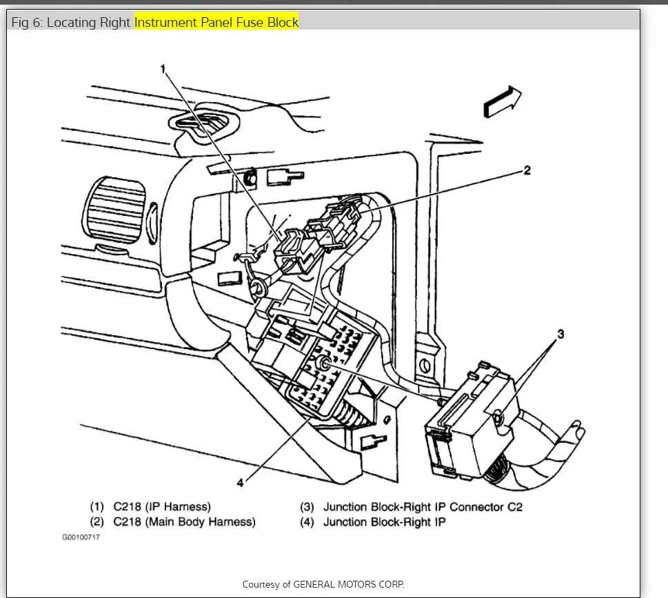
If you’re troubleshooting electrical issues in your Chevrolet sedan, understanding the location and function of key connectors is essential. The main distribution area is situated within the cabin, typically near the driver’s side, under the dashboard. Ensure that the vehicle’s power is off before starting any work to avoid electrical shocks or damage to the system.
Start by checking the connectors inside the cabin. These are usually located on the left side of the vehicle, beneath the dashboard. You may need to remove a panel or cover to access them. Pay close attention to the specific pin configurations and their corresponding circuits.
Be aware of the marked terminals, as they indicate critical connections, including power, ground, and accessory circuits. If you notice any corrosion or loose terminals, this could be the source of power loss or malfunction. A multimeter will be your best tool to check for continuity or voltage at the terminals.
When replacing or testing individual connectors, always use the correct size and type of fuse. The wrong fuse could lead to further electrical problems or even cause a fire hazard. Make sure to cross-check the manufacturer’s specifications before proceeding with any repairs or replacements.
Wiring Layout for the Vehicle’s Electrical Components

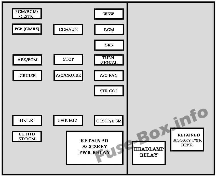
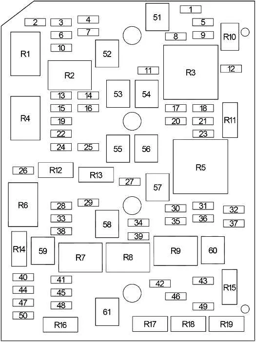
To ensure proper functionality of the vehicle’s electrical system, locate the primary connection panel under the dashboard and near the engine compartment. The specific arrangement includes various slots for relays and fuses, each serving distinct circuits like lighting, power windows, air conditioning, and the ignition system.
For the interior cabin, check the panel on the driver’s side, which controls essential features such as the radio, heating, and airbags. The external setup manages the power distribution for headlights, horn, and other crucial sensors. It is recommended to carefully follow the label codes on the cover for quick identification and replacement of faulty components.
If any malfunction occurs, consult the component listing to identify the circuit linked to the failed device. Always ensure that the correct amperage is used when replacing any of the elements to avoid overloading or further damage to the vehicle’s electrical system.
For safety, always disconnect the battery before inspecting or replacing any parts in the system, and refer to the vehicle’s owner manual for the most accurate details regarding component placement and maintenance instructions.
Locating the Electrical Panel in a 2006 Sedan

The primary location of the electrical component panel is beneath the dashboard on the driver’s side. To access it, remove the lower trim beneath the steering wheel. Once removed, you will notice a rectangular access cover. The panel is directly behind this cover and can be reached without much effort.
For additional components, there is a second panel under the hood, near the engine bay. This one is typically found on the driver’s side, close to the windshield. It is housed in a black plastic container, secured with clips. Ensure the engine is turned off before attempting to open this compartment to prevent any electrical hazards.
Always refer to the vehicle’s manual to confirm exact locations, as variations can occur depending on vehicle trim and configuration. Regular inspection of these panels can help prevent electrical malfunctions and ensure smooth operation of your vehicle’s systems.
Understanding the Electrical System Layout and Symbols
When working with the electrical distribution system in a vehicle, it’s essential to understand the arrangement of components and the symbols used for identification. This knowledge will allow you to troubleshoot and replace malfunctioning elements efficiently.
Start by identifying the location of the main electrical control panel. Typically, it’s positioned near the dashboard or in the engine compartment. This panel contains multiple slots designed for various connectors that manage specific vehicle functions.
The components are clearly labeled with standardized icons, each representing a different system. Understanding these symbols is critical when diagnosing issues or making replacements. Some of the most common symbols include:
- Battery: A symbol resembling a battery, indicating the power source.
- Headlights: A light bulb icon, which refers to the headlights and related circuits.
- Air Conditioning: A snowflake or fan icon indicating components related to cooling and air circulation.
- ABS: A circle with the letters “ABS”, signifying the Anti-lock Braking System.
- Horn: A trumpet-like icon for the horn circuit.
Each component should have a specific location within the panel. Typically, a map or guide accompanies the vehicle’s manual, showing the exact layout of the electrical distribution. Always ensure you reference this guide when troubleshooting to avoid confusion.
Remember to match the specifications of the components before replacing or repairing. Using the incorrect rating or part could result in short circuits or further damage to the system.
For routine checks, verify that all connectors are securely seated. Loose connections can lead to intermittent issues or complete failure of the associated systems.
How to Replace Electrical Components in a 2006 Vehicle
Start by locating the main electrical panel, typically situated near the driver’s side, either under the dashboard or in the engine compartment. Ensure the car is turned off before proceeding. Open the cover of the panel to expose the individual units that control various vehicle functions.
Identify the malfunctioning unit by checking the specific part listed in the vehicle’s manual. A visual inspection can also help–damaged or burnt-out units will often appear discolored or cracked. For testing, use a multimeter or a test light to confirm that the unit is no longer functioning properly.
Once identified, gently pull out the damaged unit using a pair of needle-nose pliers or a specialized tool. Avoid using excessive force to prevent damaging the surrounding components. Place a replacement of the same type and rating into the slot. Ensure it fits securely and that the connections are stable.
After installing the new unit, close the panel securely and test the related vehicle function to confirm that the issue has been resolved. If the problem persists, it may be worth inspecting for potential wiring issues or seeking professional assistance.